The Evolution of Active Differential Rebuilds in 2026
As automotive drivetrains have evolved, the traditional open or mechanical limited-slip differential has been largely superseded by electro-hydraulic active differentials. Units like the GKN Twinster, ZF ALSD (Active Limited Slip Differential), and Eaton eLSD rely on precisely modulated hydraulic pressure to engage internal clutch packs, enabling torque vectoring and advanced stability control. When these units fail, a standard mechanical teardown is no longer sufficient. Rebuilding an active differential requires verifying the integrity of internal hydraulic circuits before final assembly.
In modern drivetrain repair facilities, the most critical diagnostic step during an active diff rebuild is bench-testing the hydraulic apply circuits using a differential pressure transmitter. This step-by-step guide details the complete rebuild procedure for an electro-hydraulic active differential, emphasizing hydraulic verification, precise clutch pack clearances, and exact fluid specifications required for 2026 AWD and EV platforms.
Required Tools and Bench Equipment
Rebuilding an active differential bridges the gap between heavy mechanical wrenching and fluid power diagnostics. Before beginning, ensure you have the following specialized equipment:
- Hydraulic Test Bench: Equipped with a regulated 0-300 PSI fluid supply.
- Differential Pressure Transmitter: A 0-5V or 4-20mA industrial-grade transducer (e.g., Bosch or Fluke-compatible) scaled to 300 PSI, used to measure pressure decay and apply gradients.
- Precision Measuring Tools: Digital micrometers and dial indicators (0.0001-inch resolution).
- Bearing Pullers & Press: OTC 45-ton press with SKF/Timken bearing race drivers.
- Torque Wrenches: 1/2-inch drive digital torque-angle wrench (e.g., Snap-on TECHANGLE).
Expert Insight: Never use standard compressed air to test active differential hydraulic circuits. Air compressibility will yield false pressure decay readings on your differential pressure transmitter and can blow out delicate Teflon piston seals. Always use clean, low-viscosity test fluid or the specified OEM gear oil.
Step 1: Precision Teardown and Component Inspection
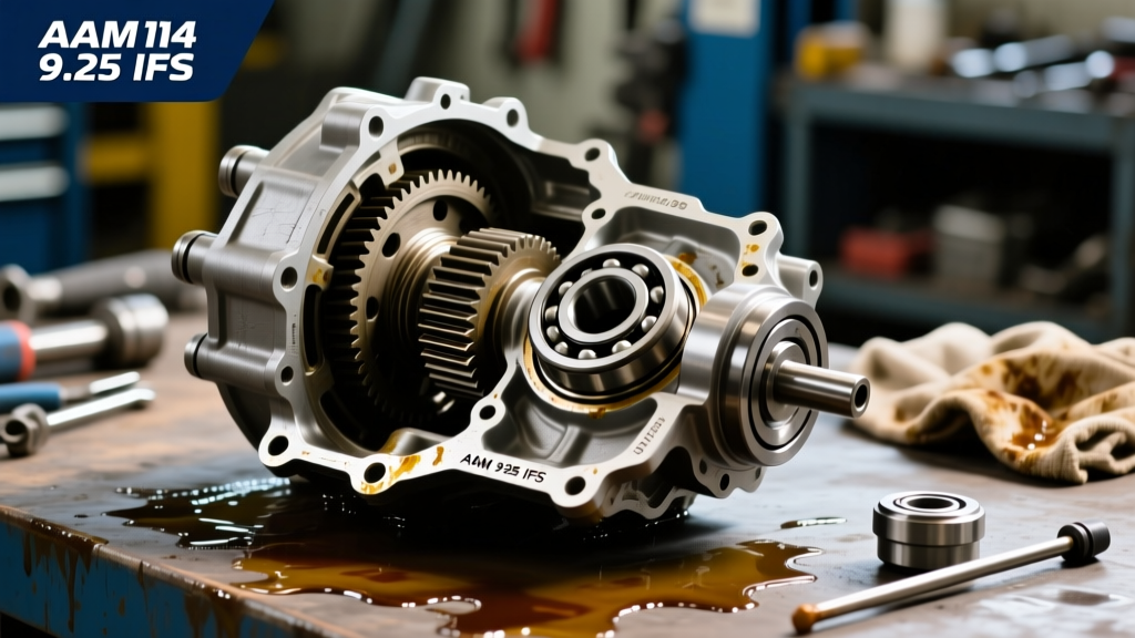
Begin by draining the differential fluid and inspecting it for metallic particulates or friction material. Active diffs typically use specialized synthetic fluids like Castrol SAF-XJ 75W-140 or OEM-specific formulations (e.g., Ford WSS-M2C942-A). If the fluid smells burnt or contains copper-colored flakes, the internal wet-brake clutch packs have experienced thermal degradation.
Disassembly Sequence
- Remove the rear cover and extract the electronic control module (ECM) and electro-hydraulic valve body. Store the valve body in a clean, lint-free environment.
- Unbolt the bearing caps (mark them for exact reinstallation) and remove the carrier assembly.
- Press the ring gear off the differential case. Inspect the ring and pinion gear teeth for pitting, spalling, or excessive backlash wear.
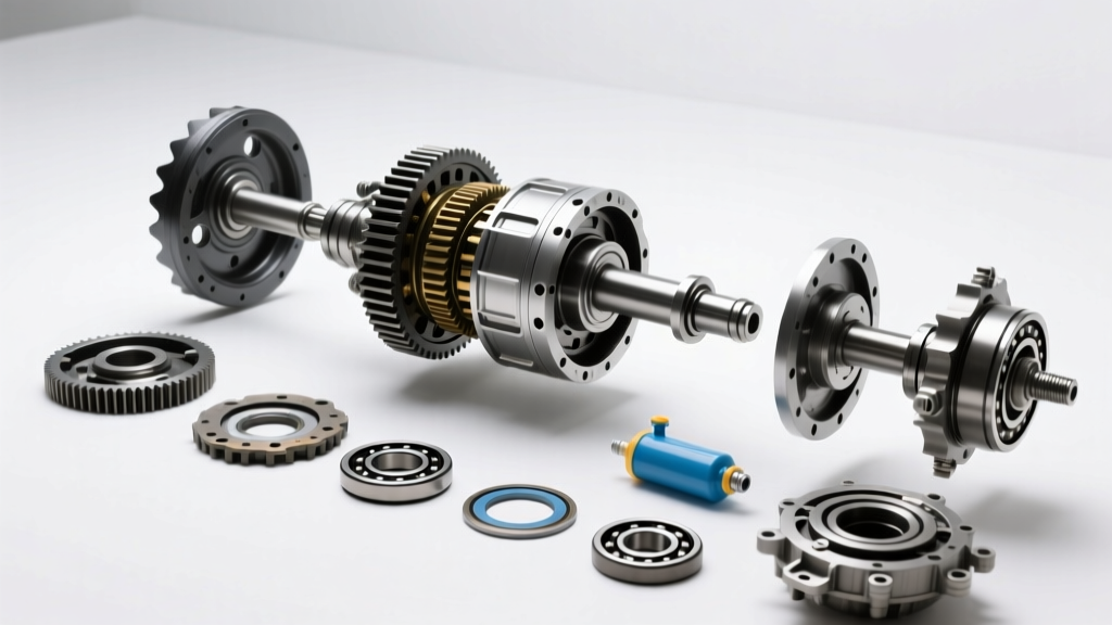
- Disassemble the internal clutch pack drum. Note the exact order of the friction plates (typically carbon-fiber lined) and steel separator plates.
Step 2: Clutch Pack Measurement and Assembly
The clutch pack is the heart of the active differential. Wear limits are incredibly tight. If the friction material is worn beyond 0.015 inches per plate, the entire pack must be replaced. When reassembling, calculating the total pack clearance is vital to prevent dragging (which causes fluid overheating) or delayed engagement (which triggers AWD fault codes).
| Differential Model | Friction Material | Total Pack Clearance | Fluid Capacity | OEM Fluid Spec |
|---|---|---|---|---|
| GKN Twinster (Ford/Opel) | Carbon-Fiber | 0.040" - 0.060" | 1.2 Liters | Castrol SAF-XJ 75W-140 |
| ZF ALSD (BMW/Audi) | Sintered Bronze | 0.035" - 0.055" | 1.5 Liters | ZF LifeguardFluid DTT |
| Eaton eLSD (GM Trucks) | Cellulose/Aramid | 0.050" - 0.070" | 2.1 Liters | ACDelco Dexron ULV |
To set the clearance, select the appropriate snap-ring or shim from your rebuild kit (typically ranging from 0.070" to 0.120" in 0.005" increments). Soak all new friction plates in the specified differential fluid for a minimum of 45 minutes prior to assembly to prevent dry-start scorching.
Step 3: Hydraulic Verification Using a Differential Pressure Transmitter
This is the most critical step for modern active differentials. Before installing the carrier back into the axle housing, you must verify that the internal hydraulic piston seals are holding pressure. A leaking piston seal will result in an inability to lock the differential under load, leading to immediate diagnostic trouble codes (DTCs) like C0394 (AWD Clutch Circuit).
Bench Testing Procedure
- Mount the assembled differential case into the hydraulic test fixture.
- Plumb the regulated test fluid line into the main hydraulic feed journal of the case.
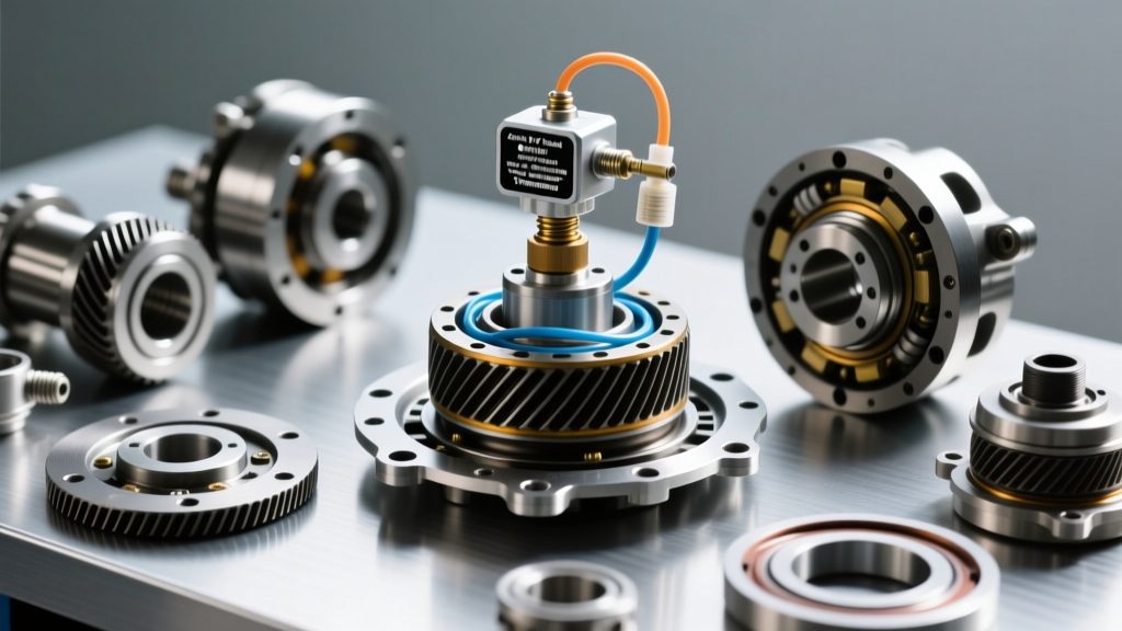
- Connect your differential pressure transmitter in-line between the fluid supply and the case journal. Ensure the transmitter is calibrated and zeroed.
- Ramp the hydraulic pressure up to the clutch's maximum apply specification (typically 220-260 PSI for most GKN and ZF units).
- Once target pressure is reached, close the supply valve to trap the fluid in the circuit.
Interpreting Transmitter Data
Monitor the readout on your differential pressure transmitter for exactly 60 seconds.
- Pass: Pressure decay is less than 2 PSI per minute. The Teflon and O-ring seals are fully seated and intact.
- Fail: Pressure drops by more than 5 PSI in 60 seconds. This indicates a cut piston O-ring, a scored cylinder bore, or a warped clutch backing plate. Disassemble and replace the seals immediately.
According to ZF Aftermarket Technical Guidelines, verifying hydraulic integrity prior to final assembly reduces warranty returns on active drivetrain components by over 80%.
Step 4: Final Assembly, Torque Sequences, and Fluid Fill
Once the hydraulic circuits pass the transmitter test, proceed with final mechanical assembly. Proper bearing preload and gear backlash are non-negotiable.
Bearing and Gear Setup
Install new carrier and pinion bearings. We recommend Timken Set 10 (LM501349/LM501314) or SKF equivalents for most mid-size active differentials. Set the pinion depth using the factory shim calculation stamped on the pinion gear head.
- Pinion Bearing Preload: 12-18 in-lbs (new bearings).
- Ring Gear Bolts: Apply Loctite 243 (Blue). Torque to 75 lb-ft, then turn an additional 90 degrees in a star pattern.
- Pinion Nut (Crush Sleeve): Tighten in 10 lb-ft increments until target rotating torque (20-25 in-lbs total) is achieved. Do not exceed 280 lb-ft; if preload is not reached, the crush sleeve must be replaced.
- Backlash: Target 0.005" - 0.008" measured at three equidistant points on the ring gear.
Fluid Fill and System Bleeding
Active differentials are highly sensitive to fluid level and aeration. Fill the housing with the exact OEM-specified fluid to the bottom of the fill plug threads. Because the electro-hydraulic valve body contains internal accumulators and galleries, the system must be bled using a bi-directional OBD2 scan tool. Command the clutch pack to engage and release 10 times to purge trapped air from the hydraulic circuit. Recheck the fluid level and top off as necessary.
Common Failure Modes and Troubleshooting
Even with a meticulous rebuild, issues can arise if underlying system problems are ignored. Here are common edge cases encountered in 2026:
- Overheating Fluid: Often caused by incorrect clutch pack clearance (too tight) or using a non-friction-modified gear oil. The differential ECM will derate torque to the axle to protect the clutches.
- Whining Noise at Coast/Load: Indicates improper pinion depth or worn ring and pinion gears. A rebuild kit will not fix gear whine; the ring and pinion set must be replaced as a matched pair.
- Valve Body Solenoid DTCs: Debris from a failing clutch pack often clogs the micro-filters in the electro-hydraulic valve body. Always replace the valve body filter screen (Part # variations apply by OEM) during any active diff rebuild.
For further engineering standards on drivetrain hydraulic testing, refer to the SAE International Standards documentation on electro-hydraulic torque vectoring systems. By integrating precision mechanical assembly with advanced differential pressure transmitter diagnostics, technicians can reliably restore active differentials to factory-new performance levels, ensuring optimal traction and vehicle dynamics.