The Evolution of Active Axles and Sensor Integration
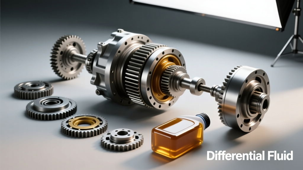
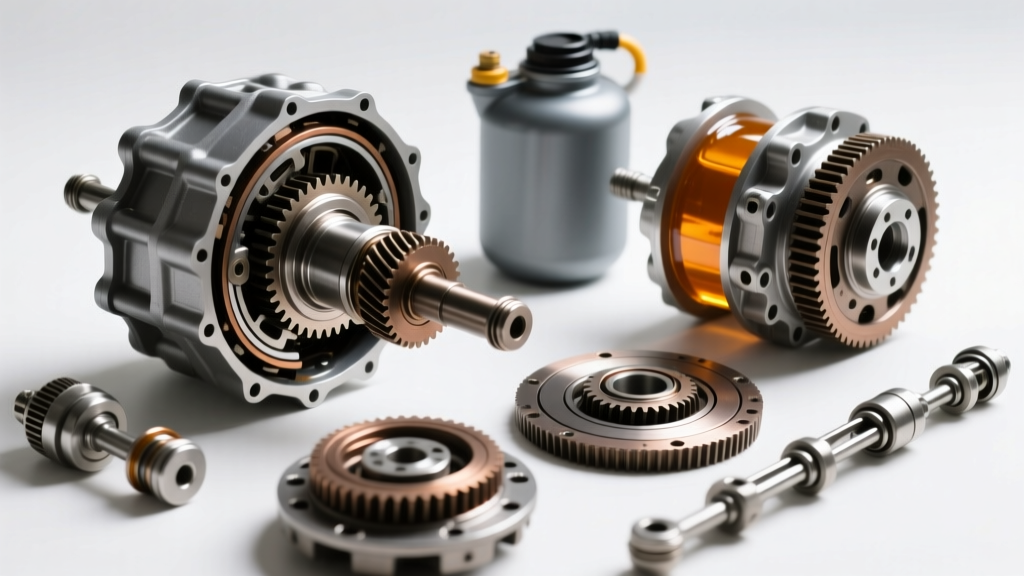
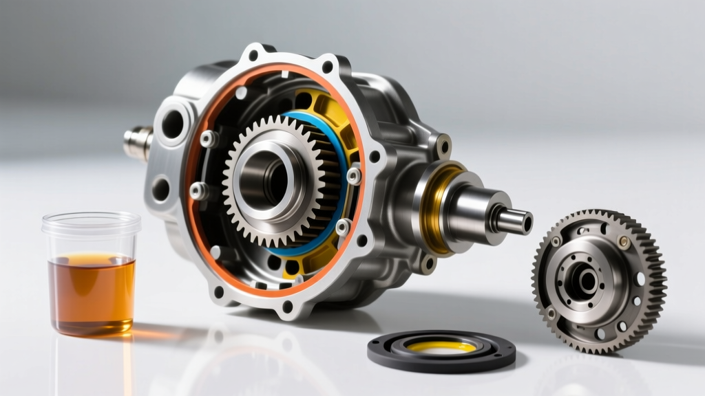
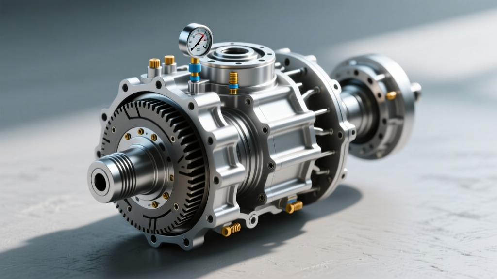
As automotive drivetrains evolve toward the 2026 model year, the traditional open or mechanical limited-slip differential has largely been replaced by active, electronically controlled torque-vectoring axles. Modern platforms, including the latest heavy-duty trucks and performance SUVs, rely on complex hydraulic clutch packs to distribute torque across the rear wheels. To manage these clutch packs, engineers have integrated sophisticated monitoring systems directly into the axle assembly. When servicing these advanced units, technicians and DIY enthusiasts must account for the differential pressure indicators built directly into the clutch pack housing and sensor arrays. Ignoring these components during a standard differential fluid change procedure can lead to catastrophic sensor failure, inaccurate clutch engagement, and severe drivetrain binding.
This comprehensive, step-by-step how-to guide will walk you through the exact differential fluid change procedure, outline critical service intervals, and detail the specific torque specifications and fluid capacities required for modern active axles equipped with internal pressure monitoring.
Why Modern Axles Feature Differential Pressure Indicators Built In
In older vehicles, a differential was a purely mechanical device relying on gear geometry and friction modifiers to manage wheel slip. Today, units like the BorgWarner eLSD (Electronic Limited Slip Differential) and ZF active rear axles utilize an internal or externally mounted hydraulic pump to apply precise clamping force to the clutch packs. The differential pressure indicators built into these systems are typically piezoresistive sensors that monitor real-time hydraulic pressure. This data is fed to the Axle Control Module (ACM) or Transmission Control Module (TCM) to ensure the clutch packs engage smoothly without shuddering or overheating.
During a fluid change, the introduction of incorrect fluid viscosity, the omission of specialized friction modifiers, or physical damage to the sensor wiring harness can cause the pressure indicators to read out of spec. This triggers a Diagnostic Trouble Code (DTC) such as C0398 (Rear Axle Clutch Pressure Sensor Circuit) and forces the differential into a fail-safe open mode, effectively disabling the traction management system.
Differential Fluid Intervals: Standard vs. Severe Duty
Determining when to change your differential fluid is highly dependent on your vehicle's operating environment. While many automakers claim their synthetic gear oils are 'lifetime' fluids under normal conditions, industry experts and lubrication engineers strongly disagree. The API (American Petroleum Institute) and independent lubricant manufacturers note that thermal breakdown and shear stability loss inevitably occur over time, especially in hypoid gear sets that operate under extreme sliding friction.
| Service Category | Interval (Miles) | Interval (Months) | Typical Operating Scenarios |
|---|---|---|---|
| Normal / Highway | 50,000 - 60,000 | 48 - 60 | Commuting, light highway driving, unladen vehicles in moderate climates. |
| Severe Duty | 15,000 - 30,000 | 12 - 24 | Frequent towing, off-roading, heavy payload, extreme cold/hot climates, stop-and-go traffic. |
| Submersion / Water | Immediate | N/A | Any instance where the axle breather tube is submerged in water, causing emulsification (milky fluid). |
For vehicles equipped with active eLSDs and internal pressure sensors, adhering to the severe duty interval (every 30,000 miles) is highly recommended. Degraded fluid loses its anti-wear properties and can cause the microscopic clutch linings to shed material, which subsequently clogs the pressure sensor ports and hydraulic pickup screens.
Step-by-Step Differential Fluid Change Procedure
The following procedure applies to modern solid rear axles (such as the Dana 80, Dana Super 60, and GM 12-bolt 9.5-inch) equipped with electronic locking or active limited-slip differentials. Always consult your specific OEM service manual for exact capacities.
Phase 1: Preparation and Sensor Protection
Tools Required: 3/8-inch drive torque wrench, 3/8-inch and 1/2-inch hex sockets, fluid transfer pump, drain pan (minimum 5-quart capacity), nitrile gloves, safety glasses, and a digital infrared thermometer.
- Warm the Axle: Drive the vehicle for 15-20 minutes to bring the differential fluid up to approximately 140°F (60°C). Warm fluid is less viscous and keeps metallic particulates and clutch material suspended, ensuring a more complete drain.
- Vehicle Elevation: Raise the rear of the vehicle using a hydraulic floor jack and support it securely on jack stands placed on the factory-designated axle tube pads. Ensure the vehicle is perfectly level; an uneven stance will result in an inaccurate fill level.
- Sensor Harness Inspection: Before touching any drain plugs, locate the wiring harness connected to the differential cover or axle tube. On active axles, the differential pressure indicators built into the assembly connect via a sealed Deutsch or Delphi connector. Inspect this connector for corrosion, brittle loom, or chafing. Disconnect the sensor plug if the OEM manual dictates removing the entire differential cover rather than using a drain plug, to prevent tearing the wiring pigtail.
Phase 2: Draining and Magnetic Plug Inspection
- Remove the Fill Plug First: This is a golden rule of drivetrain maintenance. Always remove the fill plug before the drain plug. If the fill plug is seized or stripped, you do not want to be left with an empty, immobile differential. For a Dana 80, the fill plug requires a 3/8-inch hex drive. Apply penetrating oil if necessary.
- Drain the Fluid: Remove the drain plug (or the bottom-most cover bolt if no dedicated drain plug exists). Allow the fluid to drain completely into the catch pan. Expect 3.5 to 4.5 quarts depending on the axle model.
- Inspect the Magnetic Plug: Wipe the magnetic tip of the drain or fill plug. A fine, dark metallic paste is normal wear from the ring and pinion gears. However, if you find large metallic flakes, chunks of steel, or brass-colored shavings (indicating thrust block or spider gear wear), the differential requires a full teardown and rebuild. Furthermore, check for black, fibrous debris, which indicates that the eLSD clutch packs are disintegrating.
Phase 3: Refilling and Friction Modifier Dynamics
Modern active differentials are incredibly sensitive to the frictional characteristics of the gear oil. Using a standard API GL-5 fluid without the correct friction modifier will result in clutch chatter, erratic pressure sensor readings, and premature wear.
- Install and Torque Drain Plug: Clean the threads and reinstall the drain plug. For the Dana 80, torque the drain plug to 25-35 lb-ft. For the GM 9.5-inch 12-bolt, torque to 24 lb-ft. If you removed the differential cover, clean the mating surfaces with brake cleaner, apply a 2mm bead of RTV silicone (such as Permatex Black or Ultra Grey), reinstall the cover, and torque the bolts in a crisscross pattern to 35 lb-ft.
- Add Friction Modifier (If Required): If your specific eLSD requires a standalone friction modifier (e.g., Motorcraft XL-3 or GM ACDelco 10-4016), add the exact specified amount (usually 4 to 6 ounces) into the fill hole first. Note: Many modern synthetic gear oils, such as AMSOIL Severe Gear 75W-90, already contain the necessary friction modifiers for limited-slip applications. Verify your OEM requirements to avoid over-modifying, which can cause clutch slippage and trigger low-pressure DTCs.
- Pump in Gear Oil: Using a fluid transfer pump, fill the differential with API GL-5 SAE 75W-90 or 75W-140 synthetic gear oil until it reaches the bottom edge of the fill hole. Some heavy-duty axles require the fluid level to be 1/2-inch below the fill hole; consult your manual.
- Torque Fill Plug: Reinstall the fill plug and torque to the manufacturer's specification (typically 24 to 35 lb-ft).
Post-Service Calibration and Sensor Diagnostics
For vehicles equipped with active torque-vectoring differentials and differential pressure indicators built into the hydraulic circuit, the fluid change is only half the job. The new fluid has a different viscosity profile and friction coefficient compared to the degraded fluid, which alters the hydraulic pump's duty cycle and the time it takes to achieve target clutch clamping pressure.
Using a bi-directional OBD2 scan tool capable of accessing the chassis or drivetrain control modules, you must perform a Clutch Volume Index (CVI) Reset or an Axle Clutch Relearn Procedure. This forces the ACM to recalibrate the hydraulic pump's baseline pressure maps. Skipping this calibration step can result in harsh engagements, delayed torque transfer, and false pressure sensor codes because the module will be attempting to apply clutch pressure based on the degraded fluid's parameters.
Expert Tip: After completing the relearn procedure, perform a series of tight, slow-speed figure-eight maneuvers in an empty parking lot. This cycles the hydraulic fluid through the clutch packs, purges trapped air from the pressure sensor ports, and ensures the friction modifier is evenly distributed across the clutch friction surfaces.
Conclusion
Servicing modern differentials goes far beyond simply draining and filling gear oil. As vehicles continue to integrate complex traction management systems, understanding the role of the differential pressure indicators built into the axle assembly is critical for maintaining drivetrain longevity and performance. By adhering to severe-duty service intervals, utilizing exact OEM-specified fluids and friction modifiers, and performing post-service electronic calibrations, you ensure that your active axle operates flawlessly, providing optimal traction and protecting your investment for hundreds of thousands of miles. For further reading on lubricant shear stability and gear oil classifications, refer to the SAE International Automotive Standards database.