While AutogearNexus is renowned for drivetrain and transmission friction clutch diagnostics, the car air conditioning compressor clutch represents a vital electromagnetic coupling that demands equal analytical rigor. Unlike a manual transmission clutch that relies on mechanical pedal force and hydraulic actuation, the A/C compressor clutch operates via an electromagnetic coil, engaging a friction plate to a continuously spinning pulley. When this system degrades, the symptoms often mimic internal compressor failure, serpentine belt issues, or refrigerant leaks. This technical deep-dive explores the precise wear signs, diagnostic measurements, and lifespan indicators of modern automotive A/C compressor clutches, providing the exact specifications needed for accurate troubleshooting.
The Anatomy of Electromagnetic Clutch Wear
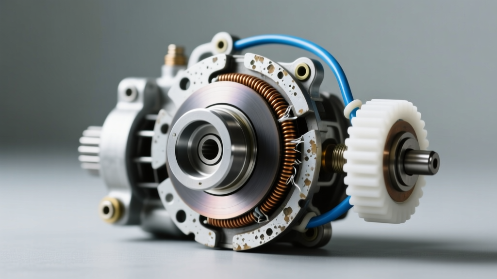
To accurately diagnose a failing car air conditioning compressor clutch, technicians must isolate the three primary mechanical and electrical sub-assemblies. Failure in any one of these components will result in a lack of cold air, but the root cause requires distinct diagnostic approaches.
- The Friction Hub (Drive Plate): Bolted directly to the compressor shaft, this steel plate contains the friction material or machined surface that mates with the pulley. Wear here manifests as glazing, thermal warping, or physical deformation.
- The Pulley and Bearing Assembly: Driven continuously by the serpentine belt via a belt-ribbed outer ring, the pulley spins on a sealed, double-row angular contact bearing. It houses the electromagnetic coil and provides the friction surface for the hub.
- The Electromagnetic Coil: A stationary copper winding housed inside the pulley. When energized with 12V DC, it generates a magnetic field that pulls the friction hub against the pulley face, locking them together to drive the internal swash plate or scroll mechanism.
Quantifying Wear: The Critical Air Gap Specification
The most common cause of intermittent A/C engagement—often misdiagnosed as a failing pressure switch or a refrigerant leak—is an excessive air gap between the friction hub and the pulley face. As the friction surfaces wear down over thousands of engagement cycles, the gap widens. Once the gap exceeds the magnetic field's effective pull range, the clutch will slip or fail to engage entirely, especially when the engine bay is hot and electrical resistance increases.
Measuring the Air Gap
According to guidelines published by the Mobile Air Climate Systems Association (MACS), the standard air gap for most passenger vehicle A/C clutches (including Denso, Sanden, and Harrison V5/HV6 models) must fall between 0.015 inches and 0.025 inches (0.38mm to 0.63mm).
- Use a non-magnetic brass feeler gauge set to avoid magnetic interference from the coil housing.
- Insert the gauge between the friction plate and the pulley face at three equidistant points around the circumference.
- If the gap measures 0.030 inches (0.76mm) or wider, the magnetic field cannot reliably bridge the distance under high-load conditions (e.g., idling in traffic with high under-hood temperatures).
- Correction requires removing the center retaining bolt, pulling the hub, and removing one or more precision shims located on the compressor shaft to bring the gap back to the 0.020-inch sweet spot.
Electrical Diagnostics: Coil Resistance and Voltage Drop
When the friction gap is within specification but the car air conditioning compressor clutch still refuses to engage, the diagnostic focus must shift to the electromagnetic coil and its supply circuit. Heat is the enemy of copper windings; prolonged exposure to engine bay temperatures can degrade the coil's internal insulation, leading to shorted windings or an open circuit.
Ohmmeter Testing Parameters
Disconnect the electrical connector at the compressor. Set your digital multimeter (DMM) to the Ohms (Ω) setting. Measure the resistance across the coil terminals. For a standard 12-volt automotive A/C clutch coil, the acceptable resistance range at ambient room temperature (68°F / 20°C) is typically 3.0 to 5.0 Ohms.
- Reading below 2.5 Ohms: Indicates shorted windings. The coil will draw excessive amperage, potentially melting the wiring harness or tripping the ECU's solid-state relay protection.
- Reading above 6.0 Ohms or Infinite (OL): Indicates an open circuit. This is frequently caused by a blown internal thermal fuse (a one-time-use temperature limiter embedded in the coil winding to prevent fires during compressor lock-up).
Voltage Drop Under Load
A coil may test fine on the bench but fail in the vehicle due to voltage drop. Back-probe the clutch connector with the engine running and the A/C commanded ON. You must see a minimum of 11.5 volts at the connector. If system voltage is 14.2V at the battery but only 9.8V reaches the clutch, the magnetic field will be too weak to pull the hub across the air gap. This points to corroded grounds, failing relays, or degraded PCM driver circuits, not a faulty clutch.
Differentiating Clutch Slippage from System Cut-Offs
Master-level diagnostics require distinguishing between a mechanically slipping clutch and a system that is intentionally being disabled by the vehicle's powertrain control module (PCM). Modern vehicles utilize high-pressure and low-pressure transducers. If refrigerant head pressure spikes above 450 PSI (often due to a restricted condenser or failed cooling fan), the PCM will cut power to the clutch to save the compressor.
Pro Diagnostic Tip: If the clutch disengages after 5 to 10 minutes of driving, monitor the high-side pressure with a manifold gauge set while simultaneously monitoring the clutch command PID on a bi-directional scan tool. If the scan tool shows the PCM is still commanding 'A/C Clutch: ON' but the clutch has physically disengaged, you have confirmed mechanical clutch slippage or a thermal limiter trip. If the PID shows 'OFF', you are chasing a pressure or evaporator freeze-up sensor issue, not a clutch failure.
Lifespan Indicators and Failure Timelines
The lifespan of a car air conditioning compressor clutch is heavily dependent on usage frequency, under-hood temperatures, and system charge levels. Running a system with low refrigerant causes the low-pressure switch to rapidly cycle the clutch on and off (short-cycling), which accelerates friction surface wear and generates immense heat in the coil.
| Component | Average Lifespan | Primary Failure Mode | Diagnostic Indicator |
|---|---|---|---|
| Friction Hub/Plate | 120,000 - 150,000 miles | Surface glazing, thermal warping | Slippage under high head pressure; burning smell |
| Electromagnetic Coil | 150,000+ miles | Internal winding short, thermal fuse blow | Infinite or zero Ohms on multimeter; no magnetic pull |
| Pulley Bearing | 100,000 - 130,000 miles | Grease depletion, seal failure | Grinding or growling noise when A/C is OFF |
For deeper OEM-specific failure patterns and service bulletins, technicians frequently consult the Denso Aftermarket Technical Library, as Denso supplies the majority of variable-displacement compressors used in Asian and European platforms.
Replacement Protocols and Torque Specifications
When wear indicators confirm that the clutch assembly has reached the end of its service life, replacement can often be performed without evacuating the refrigerant system, provided the compressor shaft seal is intact and the internal swash plate is not seized.
Tooling and Removal
Never attempt to pry the friction hub off with screwdrivers, as this will warp the plate and damage the pulley bearing. Use a dedicated clutch puller tool (such as the OTC 4524 or equivalent application-specific threaded puller). Thread the puller into the hub's tapped holes and apply steady torque to extract the hub from the tapered or splined compressor shaft.
Reassembly and Torque Specs
Proper reassembly is critical to prevent catastrophic serpentine belt failure or immediate clutch destruction.
- Snap-Ring Seating: When reinstalling the pulley and coil assembly, ensure the internal and external snap-rings are fully seated in their grooves. A dislodged snap-ring will allow the pulley to walk forward and strike the friction hub.
- Center Retaining Bolt: The bolt securing the friction hub to the compressor shaft must be torqued precisely. For most M8 and M10 shaft threads, the specification is 11 to 15 lb-ft (15 to 20 Nm). Over-torquing can strip the soft aluminum threads of the compressor shaft; under-torquing will allow the hub to fret and destroy the shaft splines.
- Shimming: Always re-check the air gap with a feeler gauge after torquing the center bolt. If the new clutch assembly sits too tight (below 0.015 inches), the clutch will drag when disengaged, melting the friction material and destroying the pulley bearing within miles.
Summary
Diagnosing a car air conditioning compressor clutch requires moving beyond simple visual inspections. By systematically measuring the air gap with brass feeler gauges, verifying coil resistance against temperature-adjusted baselines, and utilizing scan tool PIDs to differentiate between electrical slippage and PCM pressure cut-offs, technicians can accurately pinpoint the root cause of A/C failure. Understanding these lifespan indicators and adhering to strict torque and shim specifications ensures a lasting repair, keeping the cabin cool and the drivetrain accessory systems operating flawlessly.