The Electromagnetic Accessory Clutch: Beyond the Drivetrain
While AutogearNexus is globally recognized for manual and automatic transmission friction clutch diagnostics, the modern vehicle's accessory drive system relies on a crucial electromagnetic component: the A/C compressor clutch. When drivers experience erratic compressor cycling, complete cabin heat failure, or serpentine belt squeal, the root cause often lies within this electromagnetic friction interface. Executing a proper car AC compressor clutch repair requires moving past simple 'parts swapping' and adopting a rigorous, data-driven clutch system inspection checklist. This technical deep-dive outlines the exact mechanical, electrical, and thermodynamic parameters required to diagnose and repair A/C clutch assemblies with OEM-level precision.
Phase 1: Thermodynamic & Pressure Interlock Verification
Before unbolting a single component or testing electrical circuits, a technician must verify the HVAC system's thermodynamic interlocks. The Powertrain Control Module (PCM) or dedicated HVAC module will intentionally inhibit clutch engagement if refrigerant pressures fall outside safe operational thresholds. Condemning a clutch coil without verifying system pressures is a hallmark of amateur diagnostics.
Transducer Logic and Static Pressure Testing
Modern vehicles utilize a solid-state pressure transducer rather than a simple binary pressure switch. This sensor provides a linear voltage signal (typically 0.5V to 4.5V) to the PCM, correlating to system pressure.
- Static Pressure Rule of Thumb: With the system off and ambient temperature stabilized, R-134a and R-1234yf static pressures should closely match the ambient temperature in Fahrenheit (e.g., an 85°F shop should yield ~85 psi on the manifold gauges).
- Low-Pressure Cutoff: If the low-side pressure drops below 25-30 psi, the PCM will open the clutch relay ground circuit to prevent compressor cavitation and oil starvation.
- High-Pressure Cutoff: Pressures exceeding 425-450 psi on the high side will trigger an immediate clutch disengagement to prevent catastrophic hose rupture or compressor housing failure.
If your manifold gauges indicate pressures outside these thresholds, your car AC compressor clutch repair pathway must pivot to leak detection or expansion valve (TXV/ORP) diagnostics before addressing the clutch itself.
Phase 2: Mechanical Air Gap & Hub Inspection
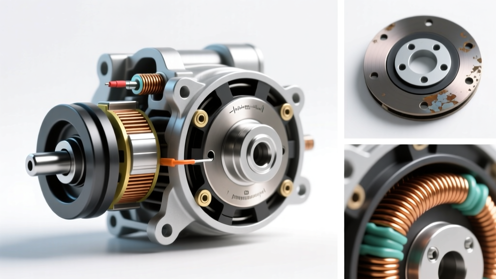
If system pressures are nominal and the PCM is commanding engagement, the next step in our clutch system inspection checklist is evaluating the mechanical air gap. The A/C clutch operates on electromagnetic induction; the stationary coil generates a magnetic field that pulls the friction plate (hub) against the spinning rotor (pulley). The distance between the friction plate and the rotor face is critical.
Measuring and Adjusting the Air Gap
Using a non-magnetic brass feeler gauge, measure the air gap at three equidistant points around the clutch perimeter.
- Target Specification: 0.020" to 0.030" (0.50mm to 0.75mm).
- Excessive Gap (>0.040"): The electromagnetic field weakens exponentially with distance. The clutch will slip under load, generating immense friction heat, glazing the friction surfaces, and eventually burning out the coil due to sustained high-amperage slip currents.
- Insufficient Gap (<0.015"): The clutch may fail to fully disengage when power is removed, causing continuous parasitic drag, premature sealed bearing failure, and excessive serpentine belt wear.
Expert Technician Note: Air gap widening is a natural consequence of friction surface wear over 100,000+ miles. Rather than replacing the entire clutch assembly, utilize a universal shim kit (e.g., Four Seasons P/N 10110). By removing the center retaining bolt and adding or subtracting precision steel shims on the compressor shaft, you can restore the air gap to factory specifications in under five minutes.
Phase 3: Electrical Circuit & Coil Integrity
When mechanical clearances are verified, the diagnostic focus shifts to the electrical circuit. The clutch coil is essentially a heavy-duty inductor. Diagnosing it requires evaluating both resistance and the protective circuitry integrated into the harness.
Ohmmeter Testing and the Snubber Diode
Disconnect the clutch harness and set your digital multimeter to the Ohms (Ω) setting. Place the probes across the clutch coil terminals. According to Mobile Air Climate Systems Association (MACS) guidelines, a standard 12V automotive A/C clutch coil should exhibit a resistance between 3.2Ω and 4.5Ω at room temperature (68°F/20°C).
- Reading < 2.0Ω: Internal winding short. The coil will draw excessive amperage, potentially melting the harness connector or blowing the HVAC fuse.
- Reading Infinite (OL): Open circuit. The internal thermal fuse has blown, or the copper winding has fractured. Coil replacement is mandatory.
The Snubber Diode: Many modern clutch harnesses feature an inline snubber diode or a diode integrated into the connector. This component suppresses the inductive voltage spike (which can exceed 100V) generated when the magnetic field collapses upon clutch disengagement. If this diode fails short, it will blow the clutch fuse immediately upon PCM engagement. Always test diode continuity in both directions if the circuit fuse is repeatedly failing.
Diagnostic Measurement Matrix
Reference this data table during your car AC compressor clutch repair to quickly isolate the failure domain.
| Test Point / Parameter | Expected OEM Value | Failure Indication & Root Cause |
|---|---|---|
| Mechanical Air Gap | 0.020" - 0.030" | >0.040" (Slipping/Glazing) | <0.015" (Parasitic Drag) |
| Coil Resistance (12V Sys) | 3.2Ω - 4.5Ω | <2.0Ω (Shorted Winding) | Infinite (Open Thermal Fuse) |
| Clutch Supply Voltage | >11.5V (Engine Running) | <10.5V (High Resistance Ground / Corroded Relay) |
| Low Side Pressure (Running) | 30 - 45 psi | <25 psi (Refrigerant Leak / TXV Blockage) |
| Center Hub Runout | < 0.010" TIR | > 0.015" (Bent Hub / Failed Sealed Bearing) |
Executing the Car AC Compressor Clutch Repair
Once the inspection checklist isolates the fault to the clutch assembly itself—whether it is a failed sealed pulley bearing, a burnt coil, or a severely glazed friction plate—the physical repair requires specific tooling and torque procedures. For deep-dive electrical schematics and component locators, resources like AA1Car's A/C Clutch Diagnostics Library provide invaluable OEM wiring references.
Component Swap vs. Complete Compressor Replacement
In the past, replacing an A/C clutch required recovering the refrigerant, unbolting the compressor, and replacing the entire unit. Today, most Sanden, Denso, and Harrison-style compressors allow for on-car clutch servicing. Using a dedicated clutch puller/installer tool (such as the Lisle 45750 set), the friction hub can be extracted without disturbing the refrigerant seals.
Critical Torque Specifications & Assembly
When reinstalling the clutch components, precision is non-negotiable to prevent catastrophic drivetrain accessory failure at highway speeds.
- Center Hub Retaining Bolt: Typically an M8 or M10 thread. Torque to 11-15 Nm (8-11 lb-ft). Apply a drop of medium-strength blue threadlocker (Loctite 243) to prevent vibration-induced backing out. Warning: Overtorquing will strip the compressor shaft threads or crack the friction plate hub.
- Pulley/Bearing Assembly: Press-fit onto the compressor snout. Ensure the snap ring groove is completely clean before seating the retaining ring. The snap ring must be fully seated with the beveled edge facing outward.
- Coil Alignment: Ensure the anti-rotation tab on the coil housing is perfectly seated in the compressor housing notch. If the coil rotates during operation, it will sever the wiring pigtail within minutes.
Final System Validation
Completing the car AC compressor clutch repair is only half the battle. Post-repair validation requires monitoring the clutch engagement cycle via a scan tool while observing manifold gauges. The clutch should engage within 1-2 seconds of the HVAC module command, pulling the low-side pressure down smoothly without erratic fluttering. By adhering strictly to this clutch system inspection checklist, technicians can eliminate guesswork, prevent premature warranty returns, and restore optimal thermodynamic efficiency to the vehicle's accessory drivetrain.