The Mechanics of A/C Clutch Drag and Release Failures
When diagnosing automotive HVAC systems, few issues are as deceptive as clutch drag and release problems. Unlike manual transmission clutches that rely on hydraulic pressure and mechanical linkages, an automotive A/C compressor clutch is an electromagnetic device. When 12 volts are applied to the electromagnetic coil, it generates a magnetic field that pulls the friction plate (hub) against the spinning pulley, engaging the compressor shaft. When the PCM or thermostat cuts the power, the magnetic field should collapse instantly, and a wave washer (damper spring) pushes the friction plate back to its resting air gap.
However, when testing AC compressor clutch circuits, technicians frequently encounter two distinct failure modes: clutch drag (where the pulley bearing fails, or residual magnetism keeps the plate lightly engaged) and release problems (where the clutch fails to disengage due to electrical shorts, PCM ground faults, or mechanical binding). Left unresolved, a dragging A/C clutch causes severe parasitic engine loss, accelerates serpentine belt wear, and can ultimately snap the belt, leading to catastrophic engine overheating or loss of power steering.
Essential Diagnostic Tools for 2026 HVAC Systems
Before tearing into the compressor, gather the proper diagnostic equipment. Guessing air gaps or coil health will result in repeat failures.
- Digital Multimeter (DMM): A True-RMS meter (like the Fluke 87V) is mandatory for accurate resistance and voltage drop testing.
- Feeler Gauge Set: Both metric and imperial blades are required for precise air gap measurement.
- Clutch Hub Puller: A dedicated puller (e.g., OTC 4521 or Lisle 45950) prevents damage to the compressor snout threads.
- Dial Indicator: For measuring pulley lateral runout and bearing deflection.
- Digital Storage Oscilloscope (DSO): Essential for modern vehicles utilizing Pulse Width Modulation (PWM) clutch control.
Step 1: Isolating Mechanical Drag (Pulley and Bearing)
The first step in diagnosing clutch drag is eliminating the pulley bearing as the culprit. The A/C clutch pulley rides on a sealed, double-row angular contact bearing that spins continuously whenever the engine is running, regardless of whether the A/C is turned on.
Bearing Deflection and Runout Testing
Remove the serpentine belt and spin the A/C clutch pulley by hand. The rotation should be smooth, with a slight viscous drag from the bearing grease. If you feel gritty resistance, hear a metallic growl, or notice lateral wobble, the bearing has suffered grease starvation or brinelling from belt tension overload.
Mount a magnetic dial indicator against the outer edge of the pulley and rotate it 360 degrees. According to Mobile Air Climate Systems Association (MACS) guidelines, lateral runout should not exceed 0.015 inches (0.38 mm). Excessive runout indicates a bent pulley or a failing bearing race, which will cause the friction plate to drag against the pulley face even when the coil is fully de-energized.
Step 2: Electrical Testing for Release Problems
If the mechanical bearing is sound, the next phase of testing AC compressor clutch systems focuses on electrical release failures. A clutch that refuses to disengage when the A/C is switched off is usually the victim of residual magnetism or a control circuit fault.
Coil Resistance and Voltage Drop Tests
Disconnect the electrical connector at the compressor. Set your multimeter to Ohms and measure the resistance across the clutch coil terminals. For standard 12-volt systems, a healthy coil typically reads between 3.0 and 5.0 ohms. A reading of infinity indicates an open circuit (burnt coil), while a reading below 2.5 ohms indicates shorted windings, which can cause the coil to overheat and warp the friction plate, leading to mechanical binding.
Next, check for voltage leaks. With the ignition ON and the A/C OFF, back-probe the control wire at the compressor connector. You should read 0.00 volts. If you detect residual voltage (even 1.5 to 2.0 volts), the PCM driver transistor may be failing, or there is a short to power in the wiring harness. This low-level voltage is enough to generate a weak magnetic field, causing the clutch to drag and slip continuously, generating immense heat.
The Residual Magnetism Test
Electromagnetic coils can sometimes retain a weak magnetic charge after power is removed, especially if the coil has been subjected to extreme under-hood temperatures. To test this, energize the clutch directly with a fused 12V jumper wire, then remove the ground. Immediately touch a small steel screwdriver to the friction plate. If the screwdriver sticks or the plate resists being pulled away by the wave washer, the coil is suffering from residual magnetism and must be replaced.
Step 3: Measuring and Adjusting the Clutch Air Gap
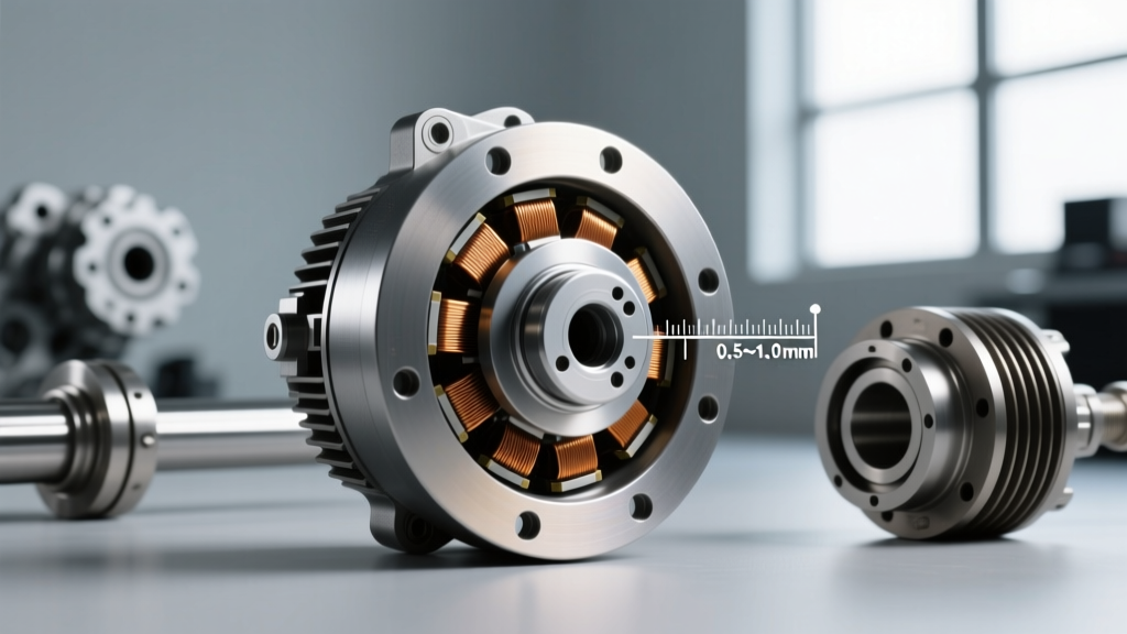
The air gap is the distance between the pulley face and the friction plate when the clutch is disengaged. If the gap is too narrow, thermal expansion and pulley runout will cause the clutch to drag. If the gap is too wide, the magnetic field cannot overcome the resistance, resulting in slipping and burnt friction surfaces.
Insert a feeler gauge through the inspection slots in the friction plate. Measure the gap at three equidistant points around the circumference to account for any minor warping.
| Compressor Model | Target Air Gap | Coil Resistance (12V) | Center Bolt Torque |
|---|---|---|---|
| Denso 10S17C / 10PA17C | 0.015 in. - 0.028 in. (0.4 - 0.7mm) | 3.0 - 4.0 Ohms | 11 - 15 Nm (8 - 11 lb-ft) |
| Sanden SD7V16 / SD7H15 | 0.016 in. - 0.031 in. (0.4 - 0.8mm) | 3.5 - 4.5 Ohms | 12 - 16 Nm (9 - 12 lb-ft) |
| Delphi / Harrison HT6 / CVC | 0.020 in. - 0.030 in. (0.5 - 0.75mm) | 3.2 - 4.2 Ohms | 15 - 20 Nm (11 - 15 lb-ft) |
| Zexel / Valeo DCS17C | 0.018 in. - 0.025 in. (0.45 - 0.65mm) | 3.0 - 3.8 Ohms | 10 - 14 Nm (7 - 10 lb-ft) |
The Reshimming Procedure
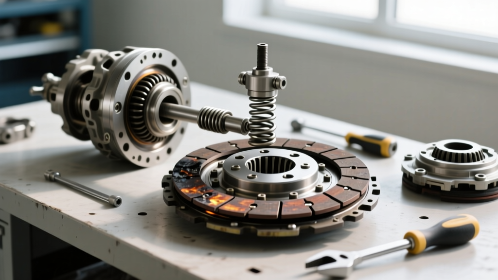
If your measurement falls outside the specifications listed above, you must adjust the shims located behind the friction plate hub. Use your clutch hub puller to remove the center bolt and extract the friction plate. Behind the plate, on the compressor shaft, you will find a stack of precision steel shims (typically 0.1mm, 0.3mm, and 0.5mm thick).
To increase the air gap (fix a dragging clutch), add shims. To decrease the air gap (fix a slipping clutch), remove shims. Reinstall the friction plate and torque the center bolt to the manufacturer's specification. Never use an impact wrench on the center bolt, as the shock loading can shatter the internal ceramic thermal limiter found in modern variable displacement compressors.
Step 4: Diagnosing Thermal Limiters and PWM Release Signals
In modern 2026 vehicles, A/C systems frequently utilize variable displacement compressors with PWM-controlled clutches or internal thermal protection fuses. Understanding these systems is critical when diagnosing release problems.
PWM Clutch Slip vs. Mechanical Drag
Many late-model European and Asian vehicles use a PWM signal to intentionally 'slip' the A/C clutch at a 40% to 60% duty cycle. This reduces parasitic drag on the engine and improves fuel economy. If you use a standard multimeter, this PWM signal may look like a low-voltage fault or a dragging clutch. You must connect a DSO to the control wire to verify the square wave pattern. If the PCM is commanding a 50% duty cycle, the clutch is designed to slip slightly; this is normal operation, not a release failure.
Internal Thermal Limiters
Compressors like the Sanden SD7V16 feature an internal thermal limiter (a sacrificial ceramic fuse) integrated into the clutch hub. If the clutch slips excessively due to a wide air gap or low refrigerant charge, the friction plate heats up. Once the hub reaches approximately 135°C (275°F), the thermal limiter melts, permanently severing the mechanical link between the pulley and the compressor shaft to prevent a belt fire. If your clutch pulley spins freely but the center hub does not, and electrical testing confirms the coil is energizing, the thermal limiter has blown. The entire clutch assembly must be replaced, and the root cause of the overheating (e.g., low refrigerant, blocked condenser) must be addressed.
Cost Analysis: Reshimming vs. Full Compressor Replacement
When testing AC compressor clutch assemblies, determining the economic repair path is essential for the customer. Here is a breakdown of typical 2026 aftermarket and OEM pricing:
- Shim Kit & Bearing Replacement: $15 - $35 for shims; $40 - $75 for a high-quality NSK or NTN pulley bearing. Labor adds 1.5 hours. Total: ~$180 - $250.
- Complete Clutch Assembly (Coil, Pulley, Hub): $90 - $160 for aftermarket (e.g., Four Seasons, GPD); $250 - $400 for OEM Denso/Sanden. Labor adds 1.5 hours. Total: ~$250 - $550.
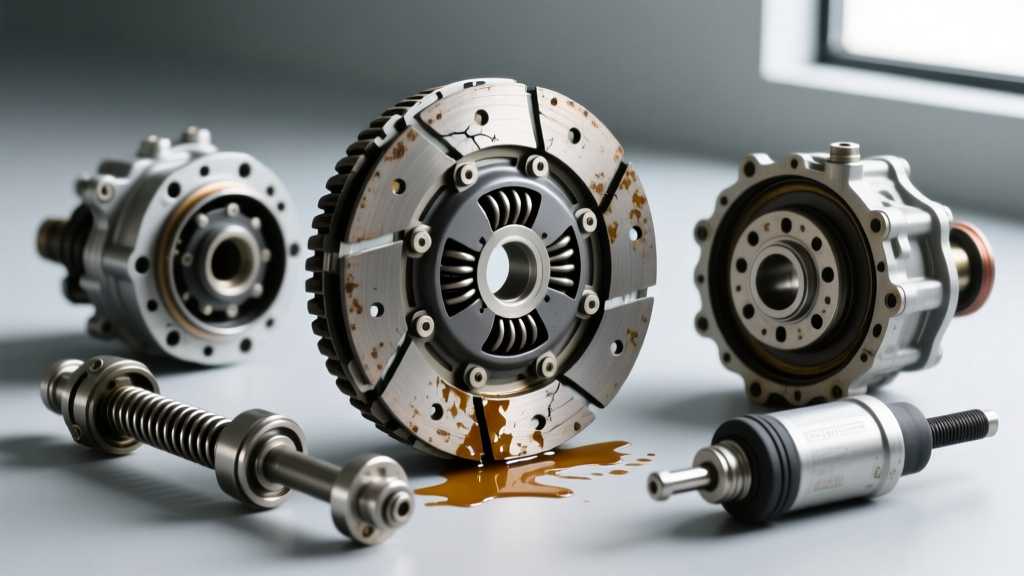
- Full Compressor Replacement: Required if the internal shaft seal is leaking onto the clutch friction surface (causing hydraulic drag and slip). Compressor costs range from $250 to $600, plus $150 for a flush kit, new expansion valve, and receiver drier, plus 2.5 hours labor and refrigerant. Total: $800 - $1,400.
For deeper diagnostic flowcharts and wiring schematics specific to your vehicle's PCM command logic, consult resources like AA1Car Automotive A/C Diagnostics or the technical bulletins available at HVAC School. Accurate diagnosis relies on methodical elimination of mechanical, electrical, and control-system variables.