The Anatomy of a Burnt Clutch Smell
When you pull the dipstick of a late-model vehicle or drain the pan of a sealed unit and are greeted by the acrid, unmistakable odor of burnt toast or charred paper, you are witnessing the chemical death of your automatic transmission fluid (ATF) and the physical destruction of your clutch packs. In modern 8-speed and 10-speed automatics, such as the ZF 8HP or GM 10L80, the transmission relies on ultra-low viscosity (ULV) fluids. When clutch friction material delaminates due to excessive slip, the fluid's friction modifiers break down, and the base oil oxidizes rapidly, creating a distinct burnt smell and leaving behind a abrasive, conductive sludge.
Diagnosing a clutch burning smell is not just about identifying that the clutches are ruined; it is about determining why they failed. Was it a failed pressure control solenoid? A cracked clutch hub? A worn piston seal? Answering these questions requires a complete mechanical teardown, which brings us to the most critical, often misunderstood tool in the rebuild process: the transmission clutch spring compressor.
Differential Diagnosis: Clutch Pack vs. Torque Converter
Before pulling the transmission from the vehicle, you must isolate the source of the burnt fluid. A burnt smell can originate from two primary sources: the internal clutch packs or the Torque Converter Clutch (TCC).
- TCC Slip (Torque Converter): Typically presents with a shudder at highway speeds (40-65 mph) and will often trigger diagnostic trouble codes like P0741 (TCC Stuck Off) or P2637 (TCC Signal). The smell is burnt, but the fluid is usually dark brown rather than jet black with visible debris.
- Clutch Pack Slip: Presents as RPM flares or 'slipping' during specific gear changes (e.g., the notorious 2-3 shift flare on the GM 6L80). The fluid will be black, smell severely burnt, and the transmission pan will contain a thick, metallic paste mixed with friction paper material.
If your road test and scan tool data confirm clutch pack slip, the transmission must be removed, disassembled, and the clutch hubs inspected. This is where the teardown begins.
Teardown Phase: Accessing the Clutch Hubs
Once the transmission is on the bench, the bellhousing and valve body are removed to expose the clutch hubs. In a GM 6L80, for instance, you will be looking at the 1-2-3-4 clutch hub and the 3-5-R clutch hub. To inspect the friction plates, steel separator plates, and the piston seals, you must remove the heavy-duty retaining snap rings that hold the clutch pack inside the drum.
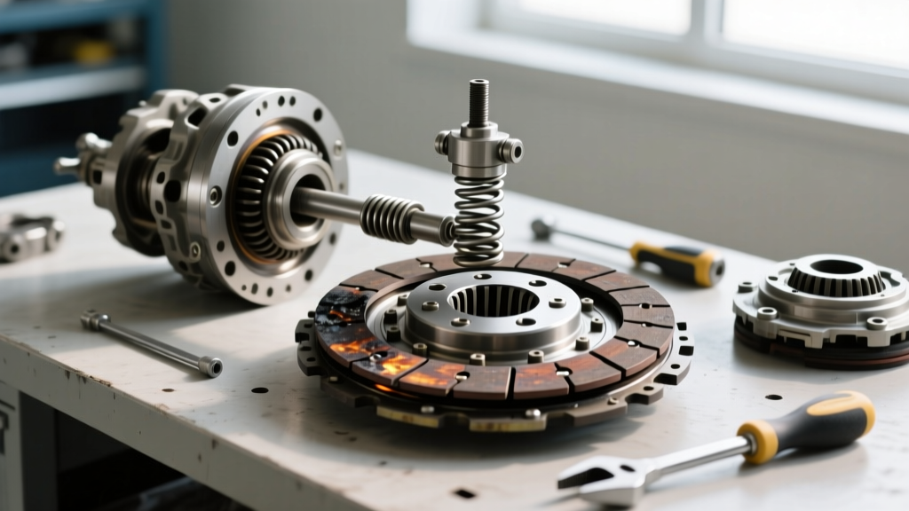
These snap rings are under immense tension from the heavy steel return springs located beneath the clutch piston. Attempting to pry these rings off with standard snap ring pliers or screwdrivers is a catastrophic mistake. The stored kinetic energy can launch the snap ring across the shop, or worse, cause severe lacerations. This is the exact scenario where a specialized transmission clutch spring compressor is strictly mandatory.
Mastering the Transmission Clutch Spring Compressor
A universal transmission clutch spring compressor (such as the widely used OTC 4557 or Mastercool equivalent, typically retailing between $95 and $180) consists of a central forcing screw, a crossbar or adapter plate, and various stepped rings to accommodate different clutch drum diameters.
Step-by-Step Compression and Disassembly
- Select the Correct Adapter: Choose the adapter ring that matches the outer diameter of your specific clutch drum. For a 4L60E 3-4 clutch drum, you will use a mid-sized stepped ring.
- Position the Tool: Place the adapter plate over the spring retainer. Insert the central forcing screw through the center of the drum and thread it into the adapter plate.
- Apply Tension: Using a ratchet or impact driver on low torque, slowly tighten the forcing screw. This compresses the heavy return springs, relieving the upward pressure against the snap ring.
- Remove the Snap Ring: Once the springs are fully compressed and the snap ring is loose in its groove, use internal snap ring pliers to safely remove the retaining ring.
- Release Pressure Safely: Slowly back out the forcing screw. Never release the tension abruptly, as the spring retainer can bind and pop out violently.
Expert Tech Note: When rebuilding high-horsepower applications or heavy-duty diesel transmissions (like the Allison 1000), technicians often upgrade to heavier aftermarket return springs to increase clutch apply pressure. A high-quality transmission clutch spring compressor with a rated capacity of at least 500 lbs of forcing pressure is required for these upgraded spring kits.
Measuring Clutch Pack Clearances: The Real Diagnosis
Once the spring compressor has allowed you to safely disassemble the clutch pack, you can finally diagnose the root cause of the burning smell. Inspect the steel separator plates for 'bluing'—a rainbow-colored heat tint indicating the steel exceeded 400°F. Inspect the friction plates for missing carbon or high-energy paper material.
The most critical diagnostic step is measuring the clutch pack clearance. If the clearance is too wide, the hydraulic piston must travel further to engage the clutch, leading to delayed engagement, excessive slip, and ultimately, the burnt smell you are diagnosing. Use a dial indicator to measure the travel distance of the clutch pack when pressing down on the top friction plate.
| Transmission Model | Clutch Pack | Target Clearance (in.) | Maximum Wear Limit (in.) |
|---|---|---|---|
| GM 6L80 / 6L90 | 1-2-3-4 Clutch | 0.040 - 0.080 | 0.100 |
| GM 4L60E | 3-4 Clutch (with wave) | 0.030 - 0.060 | 0.085 |
| ZF 8HP (All Models) | Clutch A (1st/2nd) | 0.025 - 0.055 | 0.075 |
| Ford 10R80 | Clutch D | 0.035 - 0.065 | 0.090 |
If your measurements exceed the maximum wear limit, the burning smell was likely caused by hydraulic lag. To correct this during reassembly, you must install a thicker selective backing plate or add an extra friction/steel plate if the drum depth allows. According to Sonnax, ignoring out-of-spec clearances is the number one cause of premature comeback failures in rebuilt units.
Reassembly, Torque Specs, and Final Verification
After replacing the burnt frictions, resurfacing or replacing the blued steels, and installing new piston seals, the transmission clutch spring compressor is used once again in reverse. You must compress the springs to reinstall the heavy-duty snap ring. Ensure the snap ring is fully seated in its groove; a poorly seated snap ring will blow out under line pressure, instantly destroying the newly installed clutch pack.
Critical Reassembly Torque Specifications
When reassembling the valve body and clutch hubs, precision is non-negotiable. Over-torquing can warp the valve body separator plate, causing cross-leaks that lead to clutch slip and another burnt smell within 500 miles.
- GM 6L80 Valve Body to Case Bolts: 8 - 10 Nm (71 - 89 lb-in). Use a calibrated inch-pound torque wrench, never a standard foot-pound wrench.
- ZF 8HP Mechatronic Sleeve Bolts: 4 Nm (35 lb-in). These are incredibly fragile and will strip the aluminum casing if over-tightened.
- Clutch Hub Retaining Bolts (General): Typically 15 - 20 Nm, secured with blue Loctite 243 to prevent backing out under high-RPM centrifugal force.
For comprehensive, model-specific teardown procedures and hydraulic circuit diagrams, professional technicians rely on manuals provided by the Automatic Transmission Service Group (ATSG). Skipping these reference materials is a gamble that usually results in a burnt clutch comeback.
The Cost of Ignoring the Smell
Driving a vehicle with a slipping, burning clutch pack will quickly contaminate the torque converter and the transmission cooler lines. A standard master overhaul kit (frictions, steels, seals, and gaskets) costs between $220 and $450 depending on the application. However, if the burnt debris ruins the torque converter and clogs the radiator-integrated transmission cooler, the repair bill easily jumps by an additional $800 to $1,200. By utilizing the proper diagnostic steps and specialized tools like the transmission clutch spring compressor, you ensure the repair is done safely, accurately, and permanently.
For further reading on modern transmission hydraulic diagnostics and solenoid testing, refer to the technical bulletins published by OTC Tools and major OEM service portals.