The Electromagnetic Clutch: Bridging Drivetrain and HVAC Diagnostics
While AutogearNexus primarily focuses on manual and automatic transmission drivetrain clutches, the electromagnetic A/C compressor clutch operates on the exact same fundamental principles of friction, engagement, and thermal management. When your cabin air turns warm, the immediate suspect is often the compressor itself. However, seasoned technicians know that the root cause frequently lies in the control circuit—specifically, the relay. Understanding the precise ac clutch relay location and performing a rigorous root cause analysis is the difference between a $15 fix and a $1,200 misdiagnosis. In this 2026 buyer's guide and diagnostic manual, we compare replacement relays, map out common fuse box locations, and dissect the primary failure modes of electromagnetic clutch systems.
Pinpointing the AC Clutch Relay Location Across Popular Platforms
Automakers constantly revise power distribution centers. If you are troubleshooting a no-engagement complaint, you must first isolate the control relay. Below is a comparison of the ac clutch relay location for three of the most common vehicles on the road today.
- Ford F-150 (2021-2026): Located in the Battery Junction Box (BJB) under the hood. Look for Micro Relay slot 62, labeled 'A/C CLUTCH'. This circuit is protected by a 15A mini fuse in slot 24.
- Chevy Silverado 1500 (2019-2026): Found in the Underhood Fuse Block on the driver's side. The relay is a standard ISO mini relay in position 68, designated 'A/C COMP'. It relies on a 10A fuse for the PCM control coil side.
- Honda Civic (2016-2026): Situated in the primary under-hood fuse/relay box. The relay is clearly marked 'MG CLUTCH' and is a 4-pin Omron-style relay. It shares a power feed with the condenser fan relay, making voltage drop testing critical.
Buyer's Guide: OEM vs. Aftermarket AC Clutch Relays
When root cause analysis confirms a failed relay, the next step is sourcing a replacement. The market is flooded with cheap alternatives that use inferior contact alloys, leading to rapid pitting and voltage drop. We recommend sticking to OE suppliers. Below is a comparison of the top-tier options available through major distributors like RockAuto.
| Brand / Part Number | Application / Type | Contact Rating | Avg. Price (2026) | Verdict |
|---|---|---|---|---|
| Motorcraft SW-6166 | Ford / Lincoln ISO Micro | 20A @ 14V | $14.50 - $18.00 | Best for Ford platforms; exact OE fitment. |
| Denso 156700-0840 | Honda / Toyota / Asian ISO | 30A @ 14V | $12.00 - $16.50 | Premium silver-alloy contacts; highly resistant to arcing. |
| Standard Motor Products (SMP) RY116 | Universal GM / Chrysler 4-Pin | 30A @ 14V | $8.50 - $11.00 | Excellent value; SMP's engineering specs match OE tolerances. |
| TYC 8001-0184 | Generic Multi-Fit ISO | 20A @ 12V | $4.00 - $6.00 | Budget option; prone to early contact pitting. Avoid for daily drivers. |
Expert Tip: Always apply a small dab of dielectric grease to the relay spades before insertion to prevent moisture ingress and terminal corrosion, a common issue in the 2021+ Silverado BJB designs.
Electromagnetic Clutch Failure Modes & Root Cause Analysis
Replacing the relay only solves the problem if the relay is the actual root cause. Electromagnetic clutches fail in three primary ways. Understanding these failure modes is essential for accurate diagnostics.
1. Relay Contact Pitting and Voltage Drop
The A/C compressor clutch coil draws a massive initial inrush current—often between 3.5 to 4.5 amps. Over thousands of engagement cycles, the internal contacts of the relay arc and pit. This pitting creates resistance. Instead of delivering 14.2 volts to the clutch coil, the pitted relay drops the voltage to 10.5V. Because magnetic field strength is proportional to current (and thus voltage), the weakened magnetic flux fails to pull the clutch friction plate across the air gap, resulting in a 'slipping' clutch that rapidly burns up the friction surface.
Diagnostic Check: Back-probe the clutch connector with a multimeter while the system is commanded ON. If you see battery voltage at the battery but a 2V+ drop at the clutch coil, the relay or wiring harness is the culprit.
2. Compressor Coil Thermal Breakdown
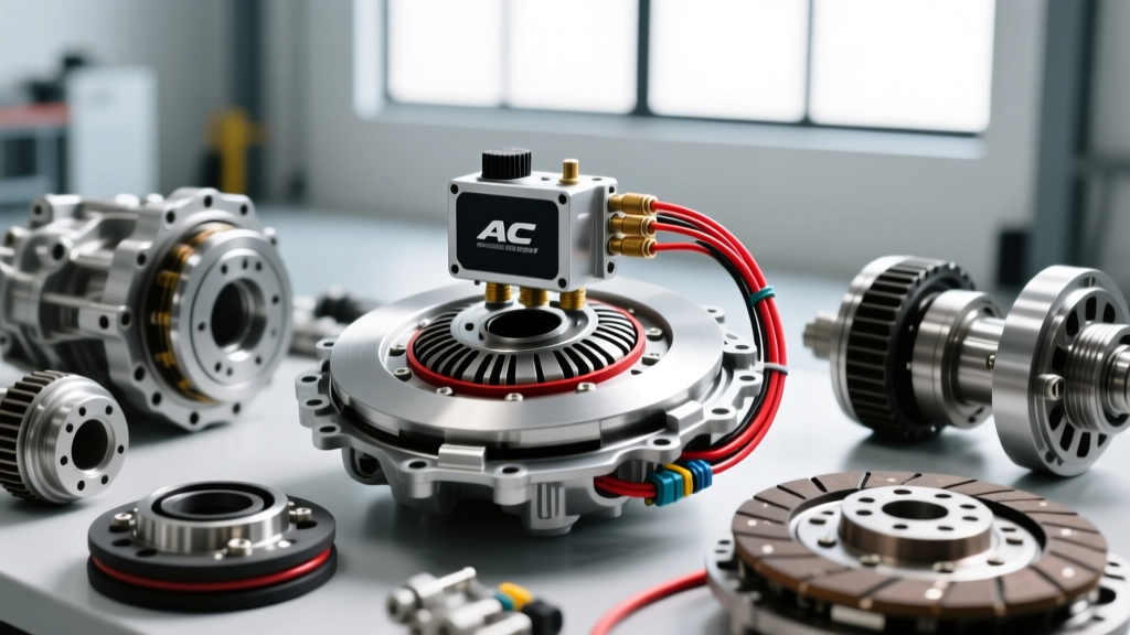
The electromagnetic coil is essentially a tight winding of copper wire encased in epoxy. Engine bay heat, combined with the coil's own internal resistance, can cause the epoxy to crack and the copper windings to short or open. According to Denso Global engineering standards, a healthy A/C clutch coil should exhibit a resistance between 3.5 and 4.5 ohms at 68°F (20°C).
Diagnostic Check: Disconnect the clutch coil and measure resistance across the terminals. If the multimeter reads 'OL' (Open Loop) or exceeds 10 ohms, the coil has suffered thermal breakdown and must be replaced. Conversely, a reading below 2.5 ohms indicates internal shorting, which will blow the A/C fuse repeatedly.
3. Air Gap Drift and Friction Wear
Just like a manual transmission clutch, the A/C clutch friction plate wears down over time. As the material wears, the 'air gap' between the rotor/pulley assembly and the friction plate increases. The factory specification for this air gap is typically between 0.020" and 0.030" (0.5mm - 0.76mm). If the gap drifts beyond 0.040", the magnetic field cannot physically bridge the distance to engage the clutch, especially when the coil is hot and electrical resistance is higher.
Repair Procedure: You do not always need to replace the entire clutch assembly. Use a snap-ring plier to remove the outer retaining ring, pull the friction plate, and remove one of the precision shims located on the compressor shaft. Reinstall the plate and torque the center M8x1.25 bolt to exactly 11-15 Nm (8-11 lb-ft). Verify the new air gap with a feeler gauge.
Advanced 2026 Diagnostics: PWM vs. Traditional Relays
As we move deeper into the 2026 model year, traditional on/off cycling clutches are being replaced by Variable Displacement Compressors (VDC), such as the Sanden SD7V16 or Denso 10S series. These systems often do not use a simple relay to cycle the clutch on and off. Instead, the clutch remains permanently engaged (or uses a heavy-duty limiter), and cooling capacity is controlled by a Pulse Width Modulated (PWM) electronic control valve inside the compressor.
If you are diagnosing a modern VDC system and cannot find a traditional ac clutch relay location, do not assume the wiring diagram is wrong. You are likely dealing with a PWM control valve failure. Diagnosing this requires an advanced bidirectional scan tool capable of commanding the compressor control valve duty cycle from 5% to 95% while monitoring high-side and low-side manifold pressures. If the clutch is mechanically locked but pressures do not equalize when the valve is commanded, the internal swashplate control valve is seized, requiring a full compressor replacement.
Summary Decision Tree
- Command A/C ON: Listen for the relay click in the fuse box.
- No Click: Check PCM ground signal and fuse. Replace relay if coil is dead.
- Click, but No Engagement: Measure voltage at clutch coil. If >13.5V, the relay is good; proceed to check coil resistance (3.5 - 4.5 ohms) and air gap (0.020" - 0.030").
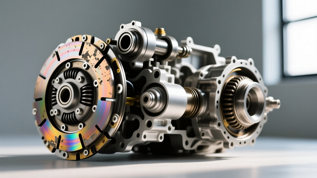
- Engages but Slips/Squeals: Check for voltage drop across the relay contacts. Clean or replace the relay, and inspect the clutch friction surface for glazing or oil contamination from a leaking front shaft seal.
By treating the A/C electromagnetic clutch with the same diagnostic rigor as a drivetrain transmission clutch, you eliminate guesswork, save money on unnecessary compressor replacements, and restore peak HVAC performance.