The Paradox: Clicking Clutch, Warm Cabin
When the AC compressor clutch engages but no cold air reaches the cabin, technicians and advanced DIYers are often misled into condemning the entire compressor assembly. However, intermittent clutch problems diagnosis requires a methodical isolation of the electromagnetic friction interface from the internal hydraulic pumping mechanism. While AutoGearNexus primarily focuses on drivetrain and transmission lock-up clutches, the electromagnetic diagnostic principles—such as coil resistance testing, air gap measurement, and thermal degradation analysis—apply directly to accessory electromagnetic clutches like the A/C compressor.
In 2026, with the widespread adoption of R1234yf refrigerant and highly sensitive electronic control modules (ECMs), the margin for error in clutch diagnostics has narrowed. A clicking relay and a visually engaged clutch plate do not guarantee torque transfer. This guide details the exact mechanical and electrical failure modes that cause an AC compressor clutch to engage intermittently or slip under load, resulting in a warm cabin despite apparent system activation.
Understanding the Electromagnetic Friction Interface
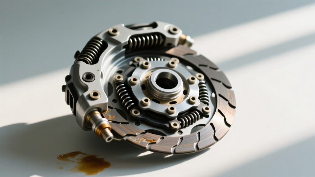
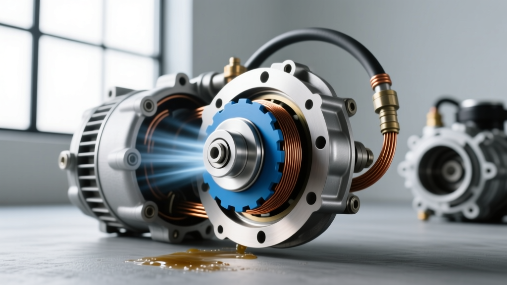
The traditional AC compressor clutch (found on fixed-displacement units like the Denso 10S17C or Sanden SD7V16) relies on an electromagnetic coil to pull a friction plate against the spinning rotor pulley. When 12V is applied, the coil generates a magnetic field that overcomes the air gap, locking the hub to the compressor's main shaft. If the clutch engages but the system fails to cool, the fault lies in one of three domains: mechanical slippage at the friction interface, electrical degradation of the coil circuit, or internal compressor failure masked by a functioning clutch.
Diagnostic Matrix: Intermittent AC Clutch Failures
Use the following matrix to quickly correlate your specific symptoms with the underlying mechanical or electrical fault. This framework is endorsed by guidelines from the Mobile Air Climate Systems Association (MACS).
| Symptom Profile | Clutch State | System Pressure | Probable Root Cause |
|---|---|---|---|
| Cools at idle, blows warm at highway speeds | Visually engaged, slipping audibly | Normal static, low dynamic | Excessive air gap / Friction plate wear |
| Cools for 5 mins, then warm; clutch clicks rapidly | Short-cycling (engaging/disengaging) | Low-side drops below 25 psi | Low refrigerant charge / Evaporator icing |
| Clutch engaged, hub spinning, no cooling | Locked and spinning | Equalized high/low pressures | Internal swashplate failure / Sheared hub key |
| Intermittent engagement only when engine bay is hot | Fails to pull in when hot | Normal | Thermal coil breakdown / High resistance |
Phase 1: Air Gap Degradation and Friction Slippage
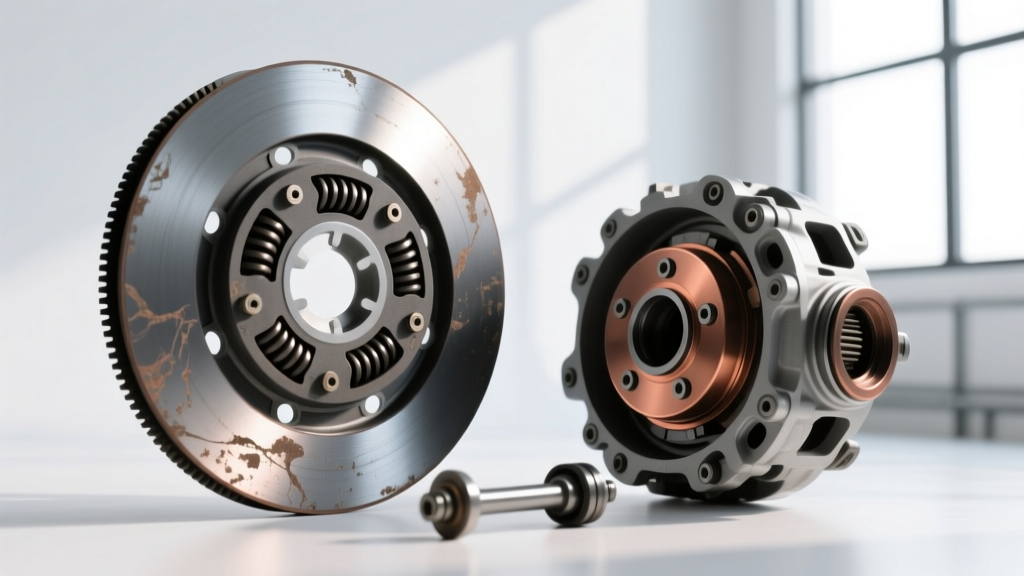
The most common cause of an AC compressor clutch engaging but failing to transfer torque—especially at higher RPMs—is an excessive air gap. Over time, the friction surfaces of the rotor and the clutch plate wear down. As the gap widens, the magnetic reluctance increases. The electromagnetic coil may have enough force to pull the clutch in when the engine bay is cool, but as ambient temperatures rise and the coil's electrical resistance increases (reducing amperage and magnetic strength), the clutch begins to slip.
Measuring and Shimming the Rotor
To diagnose air gap slippage, you must measure the distance between the rotor pulley face and the clutch friction plate. According to AA1Car Automotive AC Diagnostics, the specification for most Denso and Sanden compressors is between 0.3mm and 0.6mm (0.012" - 0.024").
- Step 1: Use a feeler gauge to measure the gap at three equidistant points around the circumference. Uneven wear indicates a bent hub or failing pulley bearing.
- Step 2: If the gap exceeds 0.6mm, the clutch will intermittently slip. You must remove the center hub bolt (typically a 10mm or 12mm hex) and extract the clutch plate.
- Step 3: Remove one of the internal shims (spacers) located on the compressor shaft beneath the clutch plate. Reinstall the plate and re-measure.
- Step 4: Torque the center hub nut to the manufacturer specification, usually 11 to 15 Nm (8 to 11 lb-ft). Over-torquing can warp the friction plate, causing localized hot-spots and premature glazing.
Phase 2: Electrical Intermittents and Thermal Coil Breakdown
If the air gap is within specification, the next suspect in intermittent clutch problems diagnosis is the electromagnetic coil itself. A failing coil will often test perfectly fine when cold but will open or exhibit massive resistance spikes when subjected to engine bay heat soak.
Thermal Resistance and Current Ramping
A standard 12V AC clutch coil should measure between 3.0 and 5.0 ohms at room temperature. However, a static multimeter test is insufficient for intermittent faults. You must perform a thermal resistance test and a current ramp test.
- Cold Baseline: Measure resistance across the coil connector pins. Record the value.
- Heat Soak: Run the vehicle until the cooling fans cycle and the engine bay reaches operating temperature. Re-measure the resistance. If the resistance jumps above 6.5 ohms or shows an open circuit (OL), the internal copper windings are breaking down under thermal expansion.
- Current Ramp: Use an oscilloscope with a low-amp current clamp. A healthy clutch coil will show an initial inrush of 8-10 amps, settling to a steady 3-4 amps. If the waveform shows erratic spikes or a gradual drop-off as the component heats up, the coil is internally shorting and must be replaced.
Expert Note: Always check the clutch relay and the wiring harness connector for corrosion. A voltage drop of just 1.5V across a corroded relay contact will reduce the magnetic pull of the coil by over 25%, leading to high-RPM slippage.
Phase 3: Internal Compressor Failure vs. Short-Cycling
Sometimes, the clutch is functioning perfectly, but the system's pressure switches are forcing it to disengage rapidly—a phenomenon known as short-cycling. To the driver, this feels like an intermittent clutch failure, but it is actually a protective measure triggered by the ECM or the low-pressure switch.
Refrigerant Charge and Swashplate Dynamics
With the transition to R1234yf, systems are highly sensitive to exact refrigerant charges. If the system is even 150 grams low on R1234yf, the low-side pressure may drop below the 25 psi threshold during idle, triggering the low-pressure switch to cut power to the clutch. As the engine revs, pressure momentarily rises, the clutch re-engages, and the cycle repeats.
Conversely, if the clutch remains visibly locked to the pulley, the center hub is spinning, but the manifold gauges show equalized high and low pressures (e.g., both sitting at 90 psi), you are dealing with an internal mechanical failure. In variable displacement compressors, a stuck electronic control valve (ECV) or a sheared internal swashplate guide pin will prevent the pistons from stroking, meaning no refrigerant is pumped despite the clutch being fully engaged.
Professional Troubleshooting Workflow
Follow this exact sequence to avoid misdiagnosis and unnecessary parts replacement:
- Visual & Auditory Check: Confirm the clutch plate is spinning with the pulley. Listen for the metallic 'scraping' sound of a slipping friction plate at 2000 RPM.
- Gauge Manifold Connection: Hook up R134a or R1234yf manifold gauges. Observe if the clutch is short-cycling due to pressure anomalies before condemning the clutch assembly.
- Air Gap Measurement: Use feeler gauges to verify the 0.3mm - 0.6mm specification. Adjust shims if necessary.
- Electrical Load Test: Bypass the vehicle wiring and apply direct 12V from a fused jumper box to the clutch coil. If it engages firmly and holds under high RPM, the fault lies in the vehicle's relay, wiring, or ECM logic.
- Internal Verification: If the clutch locks, direct 12V holds it, but pressures do not diverge (high side rising to 200+ psi, low side dropping to 30 psi), the compressor internals have failed.
Component Replacement and Torque Specifications
If diagnosis confirms the clutch assembly is faulty, you do not always need to replace the entire compressor, provided the shaft seal and internal bearings are healthy. An OEM clutch assembly (coil, pulley, and friction plate) typically costs between $80 and $150, whereas a complete compressor replacement ranges from $250 to $600 for the part alone.
When replacing the clutch coil or pulley bearing, adhere to these critical torque specifications:
- Clutch Hub Center Nut: 11 - 15 Nm (8 - 11 lb-ft)
- Compressor Mounting Bolts (M8): 20 - 25 Nm (15 - 18 lb-ft)
- Compressor Mounting Bolts (M10): 40 - 50 Nm (30 - 37 lb-ft)
By applying rigorous drivetrain-level diagnostic standards to accessory electromagnetic clutches, you can accurately isolate the root cause of an AC system that clicks but fails to cool, saving time and ensuring a permanent repair.