The Intersection of HVAC Load and Drivetrain Feel
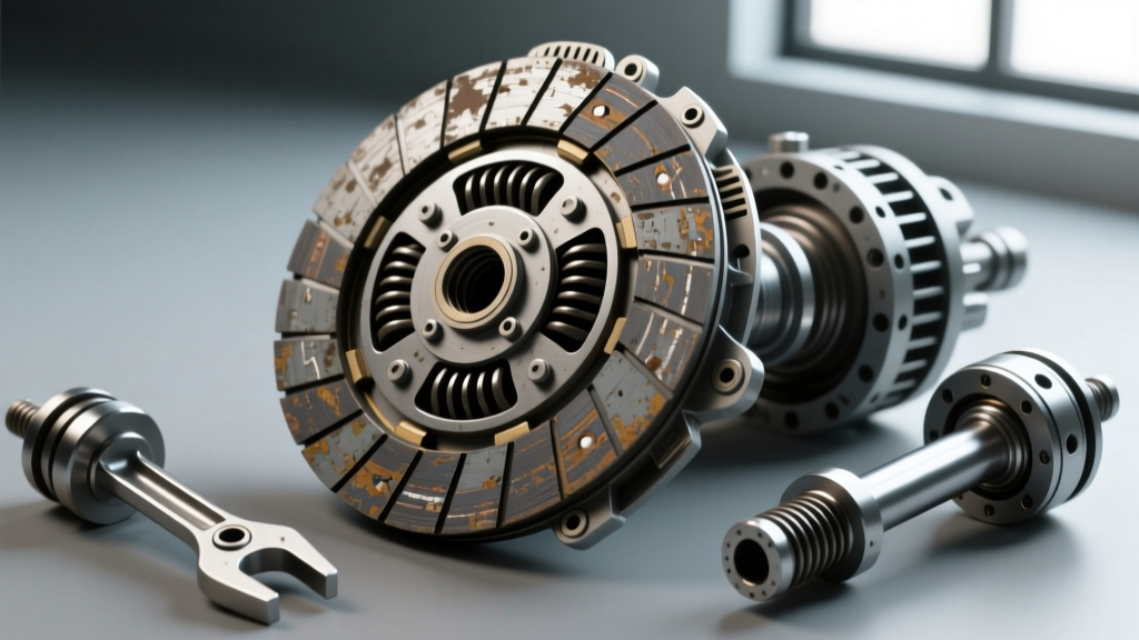
While most drivers and technicians associate clutch diagnostics with manual flywheels, dual-clutch transmissions, or automatic torque converters, the electromagnetic compressor clutch is a critical rotating assembly that directly impacts engine NVH (Noise, Vibration, and Harshness). When the ac clutch cycling switch begins to fail, it triggers a cascade of symptoms—rapid clicking, cabin vibration, and erratic idle surging—that are frequently misdiagnosed as transmission shudder, failing engine mounts, or ignition misfires.
In traditional R-134a and early R-1234yf mobile air climate systems, the compressor clutch is engaged and disengaged by a low-pressure binary or trinary switch, commonly located on the accumulator or low-side service line. This switch monitors refrigerant pressure to prevent the evaporator core from freezing and to protect the compressor from operating under low-lubrication conditions. A failing switch, or a system with marginal refrigerant charge, causes the clutch to "short-cycle," creating mechanical and electrical symptoms that mimic severe drivetrain faults. This step-by-step diagnostic guide will help you isolate the root cause of these NVH issues using precise electrical and mechanical testing protocols.
Step 1: Auditory Diagnostics – Isolating the Click
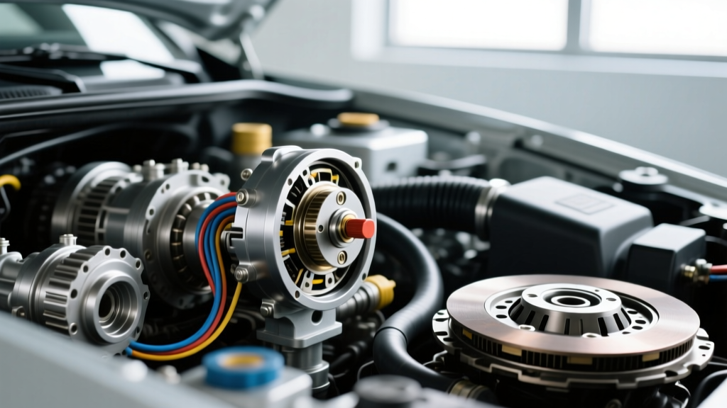
The most common initial symptom of a failing ac clutch cycling switch is a rapid, rhythmic clicking noise emanating from the engine bay, often accompanied by the HVAC blower pushing warm air. This clicking is the physical sound of the electromagnetic clutch coil engaging and disengaging the compressor's front hub plate against the pulley rotor.
Differentiating Switch Chatter from Relay Failure
Before condemning the switch or the clutch coil, you must verify the source of the click. A failing HVAC relay in the under-hood fuse box can produce an identical auditory signature. To isolate the noise:
- Visual Confirmation: Have an assistant turn the A/C to MAX while you observe the compressor clutch hub. If the hub plate is physically snapping against the rotor 3 to 5 times per second, the noise is mechanical, pointing to short-cycling.
- Relay Swap: Locate the A/C compressor relay in the power distribution center. Swap it with a known-good identical relay (e.g., the horn or fog light relay). If the rapid clicking persists, the relay is eliminated, narrowing the fault to the cycling switch, low refrigerant charge, or the clutch coil itself.
Step 2: Vibration Analysis – Load Surging vs. Misfire
When an A/C compressor clutch engages, it places a sudden parasitic load of roughly 3 to 6 horsepower on the engine's accessory drive belt. The engine control module (ECM) anticipates this load and momentarily bumps the idle air control (IAC) or electronic throttle body to maintain RPM. If the ac clutch cycling switch is short-cycling, the ECM cannot adapt fast enough, resulting in severe RPM fluctuations (e.g., dropping from 750 RPM to 550 RPM, then surging to 900 RPM).
This rapid load-shifting creates a low-frequency cabin vibration that is easily mistaken for a slipping torque converter, a warped flywheel, or degraded hydraulic engine mounts. To differentiate HVAC-induced vibration from drivetrain vibration:
- The Load-Off Test: With the engine idling and the vibration present, press the A/C OFF button or disconnect the electrical connector at the compressor clutch. If the vibration instantly vanishes and the idle stabilizes, the drivetrain is healthy, and the fault lies within the A/C control circuit or refrigerant charge.
- Steering Wheel Feedback: Drivetrain vibrations (like clutch chatter or torque converter shudder) typically manifest under load while driving or when releasing the clutch pedal. A/C short-cycling vibrations are most prominent at a standstill in Park or Neutral with the blower motor on high.
Step 3: Tactile & Electrical Testing Protocol
If auditory and visual inspections confirm short-cycling, the next step is to determine if the ac clutch cycling switch is failing internally, or if it is accurately reporting a low-pressure condition caused by a refrigerant leak. You will need a set of manifold gauges and a digital multimeter (DMM).
Manifold Gauge Verification
Connect your manifold gauges to the high and low-side service ports. Start the engine, set the A/C to MAX, and turn the blower to high. Observe the low-side gauge. A properly functioning system should show a steady low-side pressure between 28 and 40 PSI (depending on ambient temperature). If the low-side pressure is bouncing wildly between 20 PSI and 45 PSI in sync with the clutch clicking, the system is likely low on refrigerant, and the switch is doing its job by cutting power to prevent compressor damage.
Multimeter Verification of the Switch
If the static refrigerant pressure is adequate (above 50 PSI on the low side with the system off), but the clutch will not engage or continues to short-cycle, the switch itself may be mechanically stuck or electrically degraded.
- Voltage Drop Test: Back-probe the connector at the cycling switch with the ignition ON and A/C requested. You should read battery voltage (12.2V - 12.6V) on the supply wire. If voltage is present on the supply side but absent on the output side despite adequate system pressure, the internal contacts of the switch are burnt or open.
- Continuity Test: Unplug the switch and attach your DMM leads to the switch terminals. With adequate pressure in the system, the switch should show continuity (near 0.00 Ohms). If it reads "OL" (Open Loop), the switch diaphragm has ruptured or the internal spring has failed.
Reference Table: OEM Switch Thresholds & Clutch Coil Specs
Understanding the specific pressure thresholds and electrical tolerances for your vehicle is critical for accurate diagnosis. Below are standard specifications for common platforms. Always consult factory service data for exact year/make/model variations.
| Vehicle Platform | Common Switch Part Number | Cut-In / Cut-Out (PSI) | Clutch Coil Resistance (Ohms) |
|---|---|---|---|
| GM Silverado/Sierra (R-134a) | ACDelco 15-51244 | 22 / 45 PSI | 3.5 - 4.2 Ohms |
| Ford F-150 (R-134a) | Motorcraft YH1894 | 26 / 42 PSI | 3.8 - 4.5 Ohms |
| Honda Civic/Accord (R-134a) | Four Seasons 35963 | 24 / 40 PSI | 3.2 - 4.0 Ohms |
| Toyota Camry (R-1234yf) | Denko 4711630 (ECV) | N/A (Variable Disp.) | 10.5 - 11.5 Ohms (ECV) |
Step 4: Mechanical Verification and Air Gap Measurement
If the ac clutch cycling switch tests perfectly and refrigerant pressures are nominal, the short-cycling or vibration may be caused by an excessive air gap between the clutch hub and the rotor. As the clutch coil heats up during operation, its electrical resistance increases, weakening the electromagnetic field. If the air gap is too wide, the weakened magnet cannot hold the hub against the rotor, causing the clutch to slip, chatter, and disengage under load.
Using a flat feeler gauge, measure the gap between the friction surfaces of the clutch hub and the pulley rotor. The specification for nearly all modern automotive compressors (including Sanden, Denso, and Harrison/Delphi units) is between 0.4mm and 0.8mm (0.015" to 0.030"). If the gap exceeds 1.0mm, the clutch will exhibit severe chatter and vibration when hot, and the cycling switch may rapidly toggle as the system pressure spikes during momentary disengagement.
Step 5: Safe Replacement and System Re-sealing
If your diagnostics confirm the switch is the culprit, replacement is straightforward but requires strict adherence to sealing protocols to prevent future moisture ingress and refrigerant leaks.
- Depressurize Safely: Never remove a low-side switch without first recovering the refrigerant using an EPA-approved recovery machine. While some accumulator switches feature a Schrader-style valve core that theoretically allows removal under pressure, the valve cores frequently stick open or shatter on high-mileage vehicles, resulting in catastrophic refrigerant loss and PAG oil blowout.
- O-Ring Lubrication: Discard the old O-ring. Coat the new O-ring (usually included with the replacement switch) in the exact PAG oil viscosity specified for your system (e.g., PAG-46 for R-134a, ND-12 or PAG-1234 for R-1234yf). Never use standard silicone grease or petroleum jelly, as these will react with the refrigerant and destroy the compressor internals.
- Torque Specifications: Thread the new switch in by hand to prevent cross-threading the soft aluminum accumulator housing. Tighten the switch to 10-14 lb-ft (consult specific service manual, as some metric switches require a tighter 15-18 Nm spec). If replacing the manifold block or clutch coil retaining bolt, torque the center hub bolt to 11-15 lb-ft and apply a drop of blue Loctite 243.
- Vacuum and Recharge: Pull a deep vacuum to 29.9 inHg for a minimum of 30 minutes to boil off any ambient moisture introduced during the swap, then recharge to the exact factory weight listed on the under-hood emissions/HVAC decal (typically 1.2 to 1.8 lbs for most passenger vehicles).
2026 Technician Note on R-1234yf Systems: As the industry transitions fully to R-1234yf, many modern vehicles utilize variable displacement compressors controlled by an Electronic Control Valve (ECV) and a solid-state low-pressure transducer rather than a traditional binary cycling switch. If your vehicle lacks a physical clutch and cycling switch, diagnose the ECV duty cycle via a bi-directional OBD2 scan tool and monitor the transducer voltage (typically 0.5V at 0 PSI, scaling to 4.5V at 450+ PSI). For authoritative diagnostic flowcharts on both legacy and modern systems, refer to the Mobile Air Climate Systems Association (MACS) and the technical bulletins provided by AA1Car A/C Diagnostics.