Why Your 700R4 Needs an Auxiliary Cooler in 2026
The GM 700R4 (and its electronic successor, the 4L60E) is one of the most legendary overdrive automatic transmissions ever built. Found in millions of C/K trucks, Camaros, and Caprices, it is a robust unit. However, it has one Achilles' heel: heat. Automatic Transmission Fluid (ATF) begins to rapidly degrade once it exceeds 200°F (93°C). For every 20-degree increase beyond this threshold, the fluid's lifespan is cut in half. Whether you are towing a trailer, navigating stop-and-go traffic, or simply want to preserve your transmission for the long haul, installing an auxiliary cooler is the single most cost-effective upgrade you can perform.
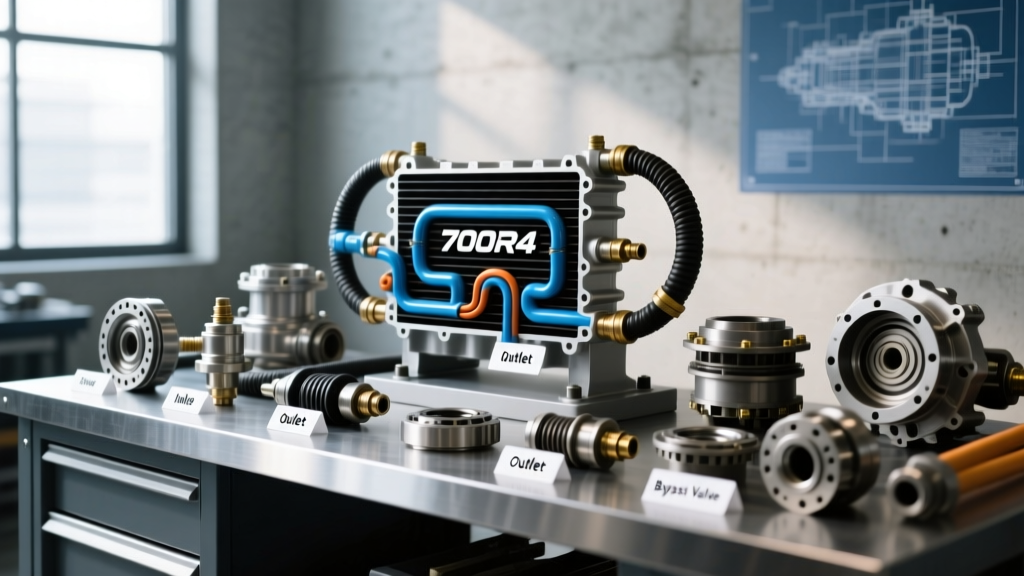
For beginners, the most intimidating part of this upgrade isn't the wrenching—it is understanding the 700R4 transmission cooler lines diagram. Routing the lines incorrectly can result in zero cooling, cavitation, or catastrophic transmission failure. This guide will demystify the flow path, help you select the right hardware, and walk you through a professional-grade installation.
Decoding the 700R4 Transmission Cooler Lines Diagram
Before you cut a single line or mount a cooler, you must understand the factory cooling circuit. The 700R4 utilizes a 3/8-inch steel hardline system. The factory routing operates in a specific sequence designed to cool the fluid while allowing it to warm up quickly in cold climates.
The Factory Flow Path
- Feed Line (Pressure Out): Hot, pressurized ATF exits the transmission case and travels to the bottom fitting of the factory radiator's internal cooler.
- Internal Radiator Cooler: The fluid flows upward through the radiator, shedding its most extreme heat spikes into the engine coolant.
- Return Line (To Trans): The fluid exits the top fitting of the radiator and returns to the transmission case.
Expert Insight: Never delete the factory radiator cooler. The factory cooler acts as a vital heat exchanger. In freezing weather, it uses engine heat to warm the thick ATF, preventing torque converter shudder and delayed shifts. Always install an auxiliary cooler in series after the radiator, not as a replacement.
The "Bucket Test": Verifying Your Diagram
While the standard GM diagram places the feed at the bottom radiator fitting and return at the top, aftermarket radiators or previous botched repairs can alter this. According to Sonnax technical resources, verifying flow direction is critical. Here is the beginner-friendly way to test it:
- Locate the two steel lines at the transmission case. Disconnect the line you suspect is the return line (usually the upper line on the trans case).
- Place the disconnected steel line into a clean catch bucket.
- Have a helper start the engine. Note: The 700R4 front pump is driven directly by the torque converter shell, meaning it pumps fluid in Park. You do not need to put the vehicle in gear.
- Run the engine for exactly 2-3 seconds. If a steady stream of red fluid fills the bucket, you have identified the return line. The line still attached to the transmission is your feed line.
- Immediately shut off the engine to prevent the transmission from sucking air into the valve body.
Choosing the Right Auxiliary Cooler
Not all coolers are created equal. For a 700R4 operating under standard to moderate towing loads, you need a unit that balances pressure drop with thermal efficiency. Here is a comparison of the three main designs available on the market today.
| Cooler Type | Design Profile | Efficiency | Best Application | Estimated Cost (2026) |
|---|---|---|---|---|
| Tube-and-Fin | Serpentine tube with exterior fins | Low (Approx. 40%) | Light duty, vintage restorations | $25 - $40 |
| Plate-and-Fin | Internal plates with turbulators | High (Approx. 75%) | Daily driving, light towing | $45 - $70 |
| Stacked-Plate | Modular aluminum plates | Maximum (Approx. 95%) | Heavy towing, off-road, racing | $80 - $150+ |
Our Recommendation: For 90% of 700R4 applications, a Plate-and-Fin cooler like the Hayden Rapid-Cool (Part #678) or the Derale Series 8000 (Part #13503) offers the perfect balance of cooling capacity and low flow restriction. Stacked-plate coolers are excellent but can sometimes cause excessive pressure drop if the internal pump is worn.
Step-by-Step 700R4 Cooler Installation Guide
Step 1: Mounting the Cooler
Ideally, the auxiliary cooler should be mounted in front of the A/C condenser and radiator to receive maximum ambient airflow. If space is tight, mounting it between the condenser and radiator is acceptable, though slightly less efficient. Use the provided nylon zip-ties and mounting pads. Pro Tip: Wrap the metal mounting tabs in electrical tape or rubber pads to prevent them from vibrating against the A/C condenser fins and causing a refrigerant leak.
Step 2: Sourcing the Correct Hose and Clamps
This is where beginners make dangerous mistakes. You cannot use standard fuel line or carburetor hose for transmission fluid. ATF runs hot and operates under higher pressures than gasoline. You must purchase SAE J1532 certified Transmission Oil Cooler Hose (3/8-inch inner diameter). Furthermore, abandon the cheap slotted worm-gear clamps; they act like a cheese grater on soft rubber hoses when pressurized. Use Fuel Injection (FI) style clamps or constant-tension spring clamps for a secure, leak-free seal.
Step 3: Routing and Splicing the Lines
Now we integrate the cooler into the 700R4 transmission cooler lines diagram. The correct flow sequence is:
- Transmission Feed Line → Radiator Bottom Fitting.
- Radiator Top Fitting (Return) → Auxiliary Cooler INLET.
- Auxiliary Cooler OUTLET → Transmission Return Line.
Cut the factory steel return line using a proper tubing cutter—never a hacksaw, which leaves metal shavings that will destroy your transmission. Slide your FI clamps onto the new 3/8" rubber hose, push the hose over the steel line at least 1.5 inches, and tighten the clamps. Route the rubber hose away from exhaust manifolds, moving suspension components, and steering shafts. Use split-loom tubing to protect the hose from abrasion.
Torque Specs, Fluids, and Final Checks
If you had to remove the adapter fittings from the 700R4 transmission case to install new lines, precision is required. The case is made of aluminum, and the threads strip easily.
- Case Fitting Torque: 15 to 18 lb-ft. Use a flare-nut (line) wrench, typically 15mm or 5/8-inch, to avoid rounding the brass or steel fittings.
- Radiator Fitting Torque: 12 to 15 lb-ft. Do not overtighten, as the radiator tanks are often plastic or thin aluminum.
Refilling and Checking the Level
Adding an auxiliary cooler and lines will increase your system's fluid capacity by roughly 0.5 to 1 quart. According to Hayden Automotive's installation guidelines, you must use the correct fluid. In 2026, Dexron VI (such as Valvoline Full Synthetic Dexron VI, approx. $9/quart) is the mandatory standard for all GM 4-speed automatics, superseding the obsolete Dexron III. Dexron VI offers superior shear stability and oxidation resistance.
The Post-Install Verification
- Add 1 quart of Dexron VI to the dipstick tube.
- Start the engine and let it idle in Park. Cycle the shifter slowly through P-R-N-D-3-2-1 and back to Park to fill the valve body and torque converter circuits.
- With the engine still idling and the transmission at operating temperature (approx. 180°F), check the dipstick. The fluid level should be in the crosshatched 'HOT' zone.
- Place a clean piece of cardboard under the new connections. Let the engine run for 10 minutes, then inspect the cardboard for any red weeping or drips.
By properly interpreting the 700R4 transmission cooler lines diagram and executing a meticulous installation, you have effectively added tens of thousands of miles to the life of your drivetrain. Heat is the ultimate enemy of automatic transmissions, and your new auxiliary cooler is the ultimate defense.