Diagnosing 68RFE Torque Converter Symptoms on the 6.7L Cummins
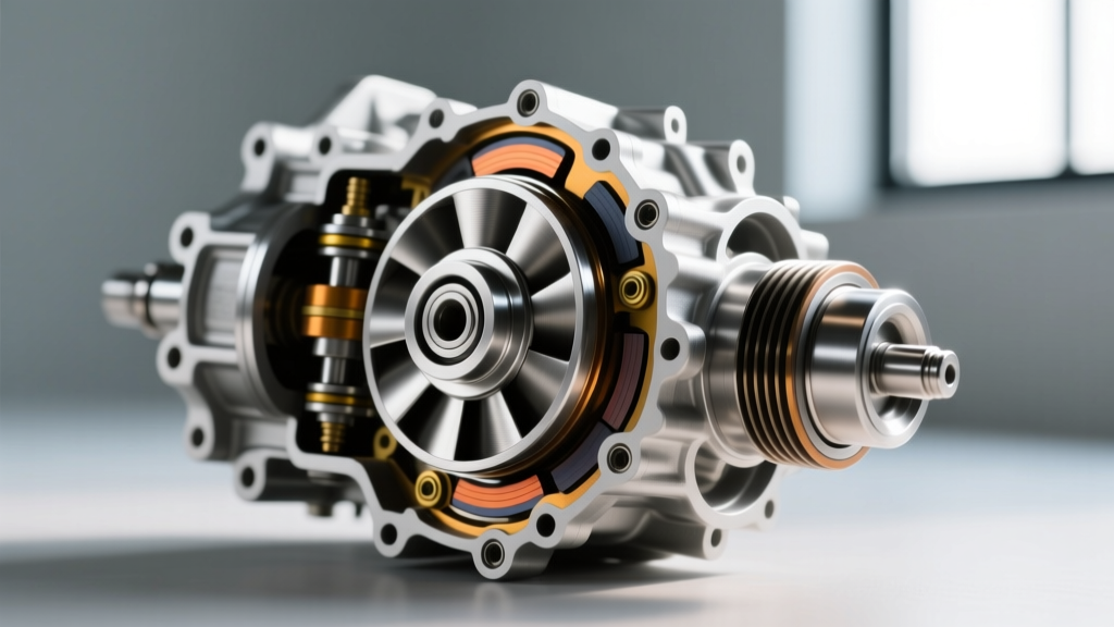
The 68RFE automatic transmission has been the workhorse behind Ram 2500 and 3500 heavy-duty trucks since its introduction. However, when mated to the high-torque output of the 6.7L Cummins turbo diesel, the factory torque converter is often the first casualty. As we evaluate heavy-duty drivetrain reliability in 2026, TCC (Torque Converter Clutch) failure remains a predominant issue for trucks running aftermarket tunes, heavier towing loads, or simply accumulating high mileage.
Before committing to a massive teardown, it is critical to verify that your symptoms actually point to the torque converter and not a failing valve body or solenoid pack. Common 68RFE torque converter failure symptoms include:
- TCC Shudder: A rhythmic vibration felt through the chassis, typically occurring between 40-55 MPH under light throttle when the converter attempts to apply the lockup clutch.
- Slip Codes (P0741 / P1740): The Transmission Control Module (TCM) detects a discrepancy between engine RPM and transmission input shaft speed during lockup.
- Overheating: A failing stator clutch or excessive TCC slip generates massive heat, often pushing transmission fluid temperatures past 220°F on the dash gauge.
- Contaminated Fluid: Dropping the transmission pan reveals a thick, glittery sludge or heavy friction material debris, indicating the single-plane OEM lockup clutch has disintegrated.
If bi-directional scanning with a tool like WiTech or AlfaOBD shows erratic TCC duty cycles and high slip RPMs despite healthy line pressures, a physical replacement is mandatory. According to transmission engineering data from Sonnax, the OEM single-disc clutch design simply lacks the surface area required to hold the 1,075 lb-ft of torque generated by modern High-Output Cummins engines without slipping.
OEM vs. Aftermarket Upgrades: 2026 Buyer’s Data
When performing a 68RFE torque converter replacement, reinstalling a factory-spec unit is rarely recommended for modified or hard-working trucks. The aftermarket has engineered multi-disc, billet-cover solutions that eliminate the weak points of the OEM design. Below is a comparative breakdown of popular options available in the current market.
| Converter Type | Part Number / Brand | Clutch Design | Stall Speed | Est. 2026 Cost |
|---|---|---|---|---|
| OEM Replacement | Mopar RL141732AA | Single-Disc TCC | ~1,600 RPM | $650 - $800 |
| Heavy Duty Towing | RevMax Stage 3 | Billet Cover, Dual-Disc | ~1,800 RPM | $1,150 - $1,350 |
| Performance / Sled | ATS TripleLoc | Billet Stator, Triple-Disc | ~2,000 RPM | $1,600 - $1,900 |
Upgraded converters from manufacturers like RevMax feature furnace-brazed fins to prevent stator deflection under high boost pressure, a common failure point that leads to catastrophic internal transmission damage.
Pre-Removal Preparation and Safety Protocols
Replacing the torque converter on a 4x4 Ram requires dropping the entire transmission and transfer case assembly. Ensure you have a high-capacity transmission jack, a heavy-duty engine support bar, and at least 18 quarts of Mopar ATF+4 (or an approved equivalent like Valvoline ATF+4) on hand.
Fluid Drainage and Transfer Case Removal
Unlike older diesel applications, many modern 68RFE torque converters do not feature a drain plug. You must drop the deep transmission pan to drain the bulk of the fluid. Expect to recover about 6 to 8 quarts from the pan. Once the pan is off, inspect the filter for large chunks of friction material. If the TCC lining has completely failed, you will find a black, abrasive paste coating the magnets and the valve body separator plate.
For 4x4 models, unbolt the rear driveshaft (marking it for balance alignment) and disconnect the shift motors and wiring harnesses from the NV271 or NV273 transfer case. Unbolt the transfer case from the 68RFE extension housing and carefully slide it backward and off the output shaft.
Step-by-Step 68RFE Transmission and TC Extraction
With the transfer case removed, support the transmission securely. Remove the crossmember and lower the assembly slightly to access the top bellhousing bolts. Disconnect the transmission cooler lines, the main wiring harness connector, and the shift linkage.
Before unbolting the bellhousing from the engine block, you must unbolt the torque converter from the flexplate. Rotate the crankshaft using a socket on the front crank bolt to access all six torque converter-to-flexplate nuts through the inspection window. Pro Tip: Use a specialized flexplate holding tool or have an assistant apply the brakes firmly to prevent the engine from turning while breaking these nuts loose.
Once the bellhousing bolts are removed, carefully slide the transmission straight back. The torque converter will either remain attached to the transmission input shaft or stick to the engine flexplate. If it sticks to the flexplate, it indicates severe input shaft spline wear or a lack of lubrication—a known issue that requires inspecting the front pump stator support bushing.
The Critical Step: Installation and the "Thunk" Test
Master Tech Warning: Never bolt the 68RFE bellhousing to the engine block if the torque converter is not fully seated. Doing so will instantly crush and shatter the transmission front oil pump gear, resulting in a $3,000+ rebuild before the truck even leaves the lift.
Proper seating of the 68RFE torque converter requires aligning three distinct components: the turbine splines on the input shaft, the stator splines on the stator support tube, and the flat tangs that drive the front oil pump gear.
- Lubricate: Coat the TC hub bushing surface and the input shaft splines with a generous layer of clean ATF+4 or assembly lube.
- Engage the Turbine: Slide the TC onto the input shaft while rotating it slightly until you feel the first drop (the turbine splines engaging).
- Engage the Stator: Continue pushing and rotating until you feel the second drop (the stator splines engaging).
- Engage the Pump: Finally, rotate the TC until the flat drive tangs align with the slots in the front pump gear. You will feel a distinct, deep "thunk" as the converter drops fully into the pump.
Verifying Seating Depth
To mathematically verify full engagement, place a straightedge across the machined mating surface of the transmission bellhousing. Measure the distance from the straightedge to the mounting pads of the torque converter. On a properly seated 68RFE torque converter, this measurement must be at least 1.0 inch (25.4mm). If the pads are flush or protruding past the bellhousing, the converter is NOT seated in the pump gear. Remove it and try again.
Essential Torque Specifications and Fluid Fill
Once the transmission is mated to the engine block and the bellhousing bolts are started, you must pull the transmission flush against the block using the bolts themselves. Never use the bellhousing bolts to pull the torque converter flush against the flexplate. The converter must slide freely forward to meet the flexplate. If there is a gap, stop and re-verify seating.
| Component | Fastener Size / Note | Torque Specification |
|---|---|---|
| Bellhousing to Engine Block | M12 / M10 Bolts | 45 lb-ft |
| TC to Flexplate Nuts | Use Medium Threadlocker | 35 lb-ft |
| Transmission Crossmember | Frame Bolts | 35 lb-ft |
| Transfer Case to Trans | Extension Housing Nuts | 25 lb-ft |
| Driveshaft Flange Bolts | 12mm / 14mm | 85 lb-ft |
After reassembly, fill the 68RFE through the dipstick tube. A dry transmission, new torque converter, and empty cooler lines will require approximately 16.5 quarts of ATF+4. Start the engine, cycle the transmission through all gears while holding the brake, and recheck the fluid level with the engine idling and the transmission at operating temperature (140°F - 160°F).
Post-Installation: TCC Adaptives and CVI Reset
The job is not complete until the TCM is recalibrated. The 68RFE utilizes adaptive learning to control the Torque Converter Clutch apply rate. If you install a new converter with a stiffer multi-disc clutch pack without resetting the adaptives, the truck will experience harsh, banging lockup engagements that can damage the driveline.
Using a bi-directional OBD2 scanner, navigate to the Transmission Adaptives menu and perform the following:
- Reset TCC Adaptives: Clears the old slip-volume data, allowing the TCM to relearn the apply volume of the new clutch discs.
- Reset CVI (Clutch Volume Index): While primarily for the internal gear clutches, resetting the CVI forces the TCM to run a complete self-diagnostic and re-measure the hydraulic volume of all clutch packs during the first 20 miles of driving.
Conduct a thorough road test, monitoring TCC slip RPMs via live data. Under steady-state highway cruising in 6th gear, TCC slip should read between 0 and 15 RPM. If slip exceeds 50 RPM consistently, re-evaluate the TCC solenoid and valve body for hydraulic leaks or cross-leaking.