The 68RFE Diagnostic Trap: External vs. Internal Sensors
The 68RFE transmission, widely deployed in 2006-2018 Ram 2500 and 3500 trucks equipped with the 5.9L and 6.7L Cummins turbo diesel engines, is a robust six-speed automatic. However, its electronic sensor network is a frequent source of driver frustration. When a Ram truck suddenly defaults to limp mode, refuses to crank, or exhibits erratic shifting, the immediate instinct for many DIY mechanics is to suspect internal hydraulic failures. This leads thousands of owners down an expensive rabbit hole, dropping the transmission pan and searching for the exact 68rfe transmission line pressure sensor location, only to realize the actual culprit is mounted entirely outside the transmission case.
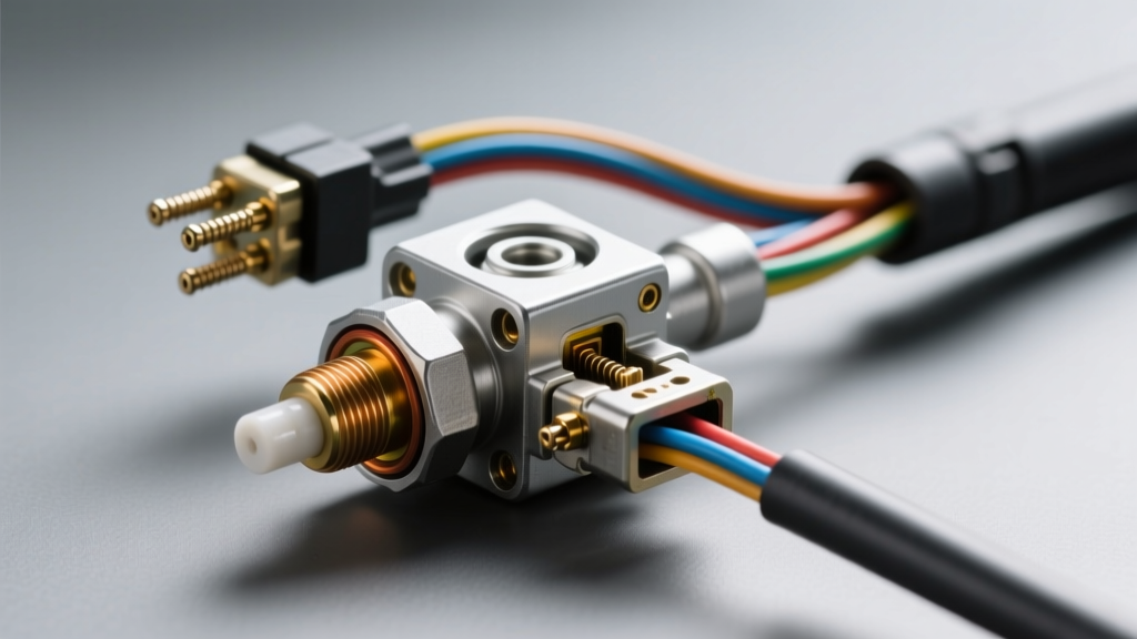
The Transmission Range (TR) sensor—often referred to as the neutral safety switch or manual lever position sensor—is an external component mounted on the driver's side of the 68RFE case. Because both the internal solenoid pack (which houses the line pressure sensor) and the external TR sensor can trigger similar limp-mode symptoms and shift-related diagnostic trouble codes (DTCs), misdiagnosis is incredibly common. As of 2026, with the aging wiring harnesses on these Cummins trucks, external sensor and pigtail failures are statistically far more likely than internal pressure sensor faults. This model-specific guide will help you accurately diagnose TR sensor problems, perform a precision replacement, and avoid the costly mistake of unnecessarily disturbing the internal valve body.
Identifying Transmission Range Sensor Problems
Before reaching for a torque wrench, it is critical to verify that the TR sensor is actually failing. The 68RFE's Transmission Control Module (TCM) relies on the TR sensor to determine the physical position of the gear selector. When the sensor's internal potentiometer tracks wear out or moisture breaches the casing, the TCM receives conflicting or null data.
Common OBD-II Codes & Symptoms
- P0705 (Transmission Range Sensor Circuit Malfunction): The most definitive code. The TCM sees an impossible combination of switch states (e.g., reading 'Park' and 'Reverse' simultaneously).
- P0706 (Transmission Range Sensor Circuit Range/Performance): Indicates the sensor signal is out of the expected voltage parameters, often caused by a misaligned sensor during a previous repair.
- P1899 (Park/Neutral Position Switch Stuck): Common when the sensor fails internally while the vehicle is in motion.
- No-Crank Condition: The starter relay circuit is routed through the TR sensor's Park/Neutral logic. If the sensor fails to register 'Park' or 'Neutral', the truck will not crank, even if the dashboard PRNDL display shows the correct gear.
- Erratic PRNDL Display: The gear indicator on the instrument cluster may flash, show a solid block, or display the wrong gear.
For a deeper dive into how the TCM interprets these specific voltage drops, the OBD-Codes P0705 Guide provides excellent baseline electrical theory for Chrysler powertrains.
Step-by-Step 68RFE TR Sensor Replacement Guide
Replacing the TR sensor on the 68RFE is a straightforward exterior job, but it requires meticulous attention to alignment and torque specifications. You do not need to drain the transmission fluid for this repair.
Tools and Parts Required
- Genuine Mopar TR Sensor (Part # RL143151AA or updated 68021384AA) - Expect to pay between $85 and $130.
- 10mm socket and ratchet
- 15mm wrench (for linkage nut)
- T15 Torx bit (for certain harness bracket retainers)
- Alignment pin (a 5/32-inch drill bit works perfectly)
- Dielectric grease and electrical contact cleaner
Removal Procedure
- Safety First: Disconnect the negative battery cables on both batteries (if equipped with a dual-battery Cummins setup) to prevent accidental cranking or TCM voltage spikes.
- Access the Sensor: Locate the TR sensor on the driver's side of the transmission case, directly behind the shift linkage lever. You may need to remove the heat shield or air intake tubing for better access.
- Disconnect Wiring: Press the release tab on the main electrical connector. Inspect the pigtail closely. Road salt and engine heat frequently cause copper oxide (green corrosion) on the pins. Clean with contact cleaner and apply dielectric grease.
- Remove Linkage: Use a 15mm wrench to remove the nut securing the manual shift lever to the transmission manual valve shaft. Slide the lever off the splined shaft.
- Unbolt Sensor: Remove the two 10mm mounting bolts securing the TR sensor to the transmission case. Slide the sensor off the shaft.
The Critical Alignment Procedure
This is where most DIYers fail. If you simply bolt the new sensor on without aligning it, you will immediately trigger a P0706 code and potentially cause the truck to start in gear.
- Rotate the transmission manual valve shaft (the stub sticking out of the case) clockwise until it clicks into the Neutral detent. Count the clicks from the Park position if necessary (Park is fully counter-clockwise; Neutral is usually the second detent).
- Take your new TR sensor and rotate its inner sleeve until the alignment marks on the sensor body line up, or until the alignment hole is perfectly clear.
- Insert your 5/32-inch alignment pin through the sensor's alignment hole into the corresponding slot on the inner sleeve. This locks the sensor in the Neutral position.
- Slide the sensor onto the manual valve shaft, ensuring the flat spot on the shaft mates with the flat spot inside the sensor sleeve.
- Bolt the sensor to the case. Torque Spec: The mounting bolts require exactly 9 Nm (80 in-lbs). Do not overtighten, as the plastic casing will crack.
- Remove the alignment pin before reinstalling the shift linkage.
- Reinstall the manual lever and torque the shaft nut to 18 Nm (13 ft-lbs).
Component Matrix: TR Sensor vs. Internal Solenoid Pack
Understanding the difference between the external TR sensor and the internal solenoid pack (which contains the line pressure sensor) is vital for accurate estimating and diagnosis. Consult the matrix below before ordering parts from Mopar Genuine Parts or aftermarket suppliers.
| Feature | External TR Sensor (Range Sensor) | Internal Solenoid Pack (w/ Line Pressure Sensor) |
|---|---|---|
| Mopar Part Number | RL143151AA / 68021384AA | 68304435AA (Varies by exact year/TCM flash) |
| Location | Exterior, Driver-side case | Interior, bolted to valve body |
| Common DTCs | P0705, P0706, P1899 | P0868 (Line Pressure Low), P0731-P0736 (Gear Ratio Errors) |
| Average Part Cost (2026) | $85 - $130 | $280 - $360 |
| Fluid Drain Required? | No | Yes (Requires pan drop, filter change, ~7 qts ATF+4) |
| Primary Failure Mode | Internal track wear, moisture ingress | Thermistor failure, pressure diaphragm rupture |
As the data illustrates, misdiagnosing a TR sensor failure as an internal line pressure issue will cost you an extra $300 in parts, $50 in fluid and filters, and several hours of labor lying under the truck. Furthermore, dropping the valve body introduces the risk of contaminating the hydraulic circuits with debris.
Post-Repair TCM Calibration and Road Test Protocol
Once the physical installation is complete, the repair is not entirely finished. The 68RFE's TCM utilizes adaptive learning tables to adjust shift pressures based on clutch pack wear and fluid viscosity. A sudden change in sensor input parameters can confuse the TCM.
Clearing Adaptives
Connect a bi-directional OBD2 scanner capable of accessing the Chrysler TCM. Navigate to the 'Special Functions' or 'Module Reset' menu and select Clear Transmission Adaptives. This forces the TCM to relearn the shift volumes and line pressure baselines from scratch. If you do not have access to a high-end scanner, disconnecting both battery cables and touching them together for 15 minutes (with the cables disconnected from the battery posts) will drain the keep-alive memory and force a hard reset of the TCM.
The Road Test
Start the truck and verify that it only cranks in Park and Neutral. Move the shifter through all gears, pausing for two seconds in each position to ensure the dashboard PRNDL indicator matches the physical lever. During the test drive, the first few shifts may feel slightly firm or soft as the Allpar Chrysler Tech adaptive algorithms recalibrate the clutch apply times. Drive the truck through at least three complete thermal cycles (heating the ATF+4 fluid to 160°F-180°F) to finalize the adaptive memory tables.
By focusing on the external Transmission Range Sensor first, you save time, money, and the hassle of dealing with the internal 68RFE line pressure sensor location unless the data absolutely demands it. Always trust the OBD-II codes and a multimeter over assumptions when diagnosing Cummins drivetrain electronics.