The Foundation of High-Horsepower Allison Hydraulics
When building a high-performance Allison 1000 or 2000 series transmission for heavy-duty towing or competitive sled pulling, managing hydraulic line pressure is the difference between a crisp, commanding shift and a burnt clutch pack. As we navigate the 2026 landscape of heavy-duty diesel tuning, the synergy between rotational data and hydraulic feedback has never been more critical. While many enthusiasts focus solely on valve body upgrades and billet shafts, the true secret to optimized shift firmness lies in the precise calibration and upgrading of your electronic sensors.
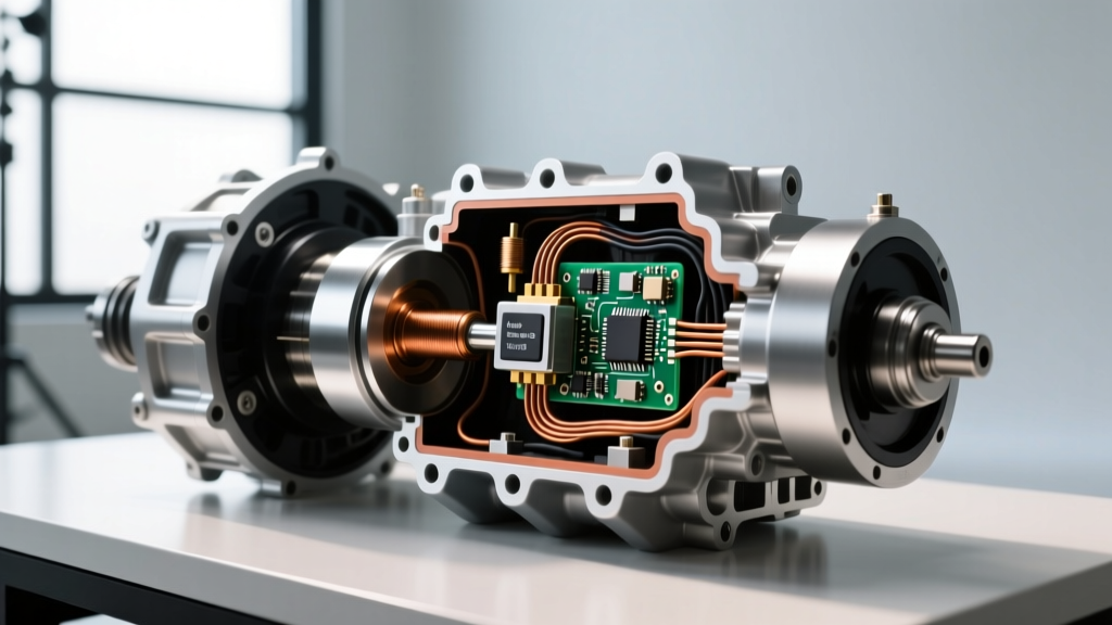
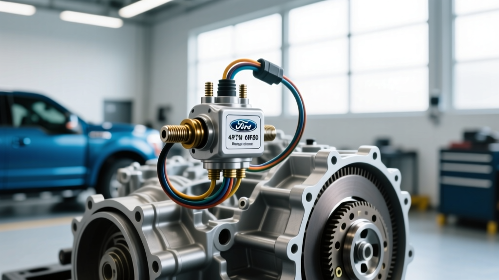
Specifically, the transmission fluid pressure sensor (TFPS) acts as the TCM’s eyes into the hydraulic circuit. However, its effectiveness is entirely dependent on accurate RPM data. This is why a holistic performance upgrade must address both the fluid pressure feedback loop and the Allison transmission speed sensor array (input and output). In this comprehensive performance and upgrade guide, we will break down the exact part numbers, torque specifications, and tuning strategies required to maximize your Allison’s hydraulic performance.
Understanding the Transmission Fluid Pressure Sensor (TFPS)
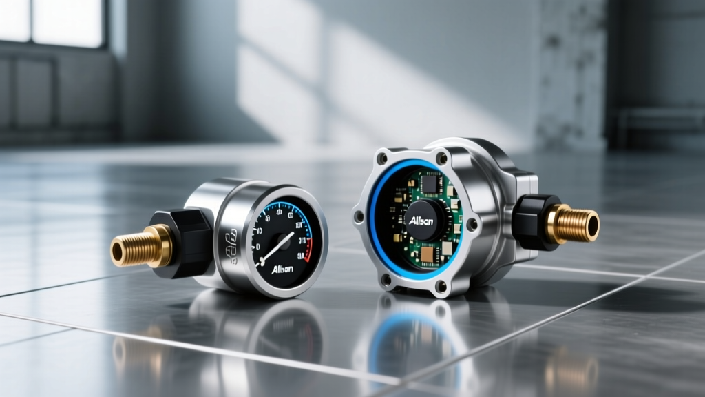
The Transmission Fluid Pressure Sensor (TFPS) is typically a piezoelectric or strain-gauge-based transducer that converts hydraulic pressure into an analog 0-5V signal. In the Allison 1000 (specifically Generations 4 and 5, commonly paired with the Duramax LBZ, LMM, LML, and L5P engines), the TCM uses this voltage to calculate actual line pressure and compare it against the desired line pressure tables in the tuning software.
How the TFPS Dictates Shift Quality
When the TCM commands a shift, it pulses the Pressure Control Solenoid (PCS) to adjust main line pressure. If the actual pressure reported by the TFPS deviates from the desired pressure, the TCM will continuously adapt the solenoid’s duty cycle. In high-horsepower applications (600+ RWHP), the factory TFPS can suffer from signal noise, voltage drop, or physical diaphragm fatigue due to extreme pressure spikes caused by aftermarket boost valves and heavy-duty accumulator springs.
- OEM Voltage Range: 0.5V (0 PSI) to 4.5V (~230 PSI)
- Performance HD Range: 0.5V (0 PSI) to 4.8V (~300+ PSI)
- Common Failure DTCs: P0875 (Transmission Fluid Pressure Sensor/Switch 'D' Circuit), P0722 (Output Speed Sensor Circuit No Signal - often misdiagnosed when pressure fluctuates wildly during slip events).
The Synergy: Why the Allison Transmission Speed Sensor Matters
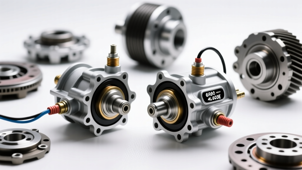
You cannot properly tune line pressure without accurate rotational data. The Allison transmission speed sensor (both the Input Speed Sensor [ISS] and Output Speed Sensor [OSS]) provides the TCM with the exact RPM of the input shaft and the tail shaft. The TCM calculates torque converter slip by comparing the ISS to the engine RPM, and it calculates gear ratio and shift timing by comparing the ISS to the OSS.
If your speed sensors are degraded, suffering from magnetic debris accumulation, or operating outside their optimal air-gap tolerances, the TCM will miscalculate shift timing. When the TCM commands a pressure spike via the TFPS circuit during a shift, but the speed sensor data is delayed or erratic, the transmission will either flare (delayed engagement) or tie-up (harsh, binding shifts). Upgrading to high-definition, sealed Hall-effect speed sensors alongside a heavy-duty TFPS ensures that your hydraulic commands are executed with microsecond precision.
OEM vs. Performance Sensor Comparison
Not all sensors are created equal. When sourcing parts for an Allison 1000 rebuild or performance upgrade, it is vital to understand the differences between standard replacements and calibrated performance units. Below is a breakdown of the most common configurations available on the market today.
| Sensor Type | Part Number / Spec | Max Pressure / RPM | Signal Noise Resistance | Estimated Cost (2026) |
|---|---|---|---|---|
| OEM TFPS | Allison 29542692 | 250 PSI | Standard (Unshielded) | $65 - $85 |
| HD Performance TFPS | Aftermarket Calibrated (e.g., PPE / BD) | 320 PSI | High (Shielded Wiring) | $120 - $160 |
| OEM Speed Sensor (ISS/OSS) | Allison 29543241 | Standard RPM | Moderate | $45 - $60 (Each) |
| HD Sealed Speed Sensor | Performance Hall-Effect Upgrade | High-RPM / Debris Resistant | Extreme (Potting Compound) | $90 - $110 (Each) |
Installation and Torque Specifications
Upgrading these sensors requires meticulous attention to cleanliness and torque specifications. The TFPS on an Allison 1000 is generally located on the valve body or the transmission case depending on the exact generation. For Gen 4 and Gen 5 applications, accessing the TFPS often requires dropping the transmission pan and removing the valve body assembly.
Step-by-Step TFPS Replacement Protocol
- Fluid Drain and Pan Removal: Use a fluid transfer pump or drain plug. Expect to capture approximately 6-8 quarts of TES-295 or TES-668 approved fluid.
- Valve Body Access: Carefully disconnect the internal wiring harness. The TFPS connector is prone to brittle locking tabs; use a pick tool to release the tension rather than pulling the wires.
- Sensor Extraction: Unthread the sensor. Inspect the O-ring and the sensor port for metallic debris. Pro-Tip: Use a borescope to inspect the valve body cavity for clutch material before installing the new sensor.
- Torque Specification: The replacement TFPS must be torqued to exactly 10 Nm (88 lb-in). Over-torquing will crack the piezoelectric ceramic element inside the sensor, leading to immediate P0875 codes.
- Speed Sensor Air-Gap: When replacing the Allison transmission speed sensor located on the case, ensure the O-ring is lubricated with clean transmission fluid. Torque the retaining bolt to 12 Nm (106 lb-in). These are zero-clearance sensors; they bottom out against the case, so no manual air-gap adjustment is required.
Expert Insight: Never use Teflon tape or liquid thread sealant on the TFPS threads. The sensor uses a precision Viton O-ring for sealing. Thread sealants can contaminate the delicate hydraulic passages of the valve body and cause the pressure control solenoid to stick.
Tuning Strategies: HP Tuners and EFILive
Hardware upgrades are only half the battle. To truly harness the capabilities of an upgraded TFPS and speed sensor array, you must modify the TCM calibration. Using platforms like HP Tuners MPVI3 or EFILive V3, tuners can manipulate the Desired Line Pressure tables to provide the clutch packs with the necessary clamping force for high-torque applications.
Mapping Desired Line Pressure
In a stock Duramax/Allison configuration, line pressure is capped to protect the factory clutch linings and accumulator pistons. When building a performance transmission with billet input shafts, heavy-duty accumulator springs, and Goerend or RevMax valve bodies, you must raise the pressure ceiling.
- Torque-Based Scaling: Instead of a flat pressure increase, map the Desired Line Pressure table against Engine Torque Request. As torque demand exceeds 400 lb-ft, scale the pressure up to 210-230 PSI.
- Shift Speed Adders: Utilize the speed sensor data to add line pressure during rapid acceleration. If the OSS indicates a high rate of change (hard launch), command an additional 15-20 PSI to prevent 2-3 and 3-4 shift flares.
- TFPS Adaptation Limits: In the TCM adaptation parameters, reduce the allowable adapt cell limits. If the actual TFPS reading deviates more than 15 PSI from the desired, you want the TCM to trigger a soft limp mode rather than continuously overworking the PCS solenoid, which generates excessive heat in the transmission fluid.
Wiring and Signal Integrity in Extreme Environments
In 2026, with the prevalence of high-output alternators and aggressive ignition systems on competitive diesel trucks, electromagnetic interference (EMI) is a leading cause of sensor failure. The 0-5V analog signal from the TFPS is highly susceptible to noise. If EMI infiltrates the signal wire, the TCM will read phantom pressure spikes, causing the transmission to abruptly dump line pressure and initiate a neutral state to protect the gearbox.
When performing a performance upgrade, always replace the factory sensor pigtails with shielded, twisted-pair wiring. Ground the shielding to the TCM ground reference, not the chassis ground, to prevent ground loops. For the speed sensors, ensure the wiring harness is routed at least 4 inches away from aftermarket high-amperage charging cables or starter power wires.
Final Thoughts on Drivetrain Electronics
A high-performance Allison transmission is a symphony of mechanical brute force and electronic precision. By upgrading your transmission fluid pressure sensor to handle higher hydraulic ceilings, and ensuring your Allison transmission speed sensor inputs are clean, shielded, and accurate, you provide the TCM with the flawless data it needs to execute race-winning or heavy-hauling shifts. Do not leave your $8,000 transmission build at the mercy of a $60 factory sensor. Invest in HD components, adhere strictly to torque specifications, and leverage modern tuning software to calibrate your hydraulic circuit for ultimate durability and performance.
For further technical documentation on hydraulic circuits and sensor tolerances, refer to the Allison Transmission official service portal, and consult Sonnax for in-depth valve body and pressure control solenoid schematics. Tuning parameters and PID logging can be further explored via the HP Tuners support documentation.