Introduction to the 4L60E Bench Build
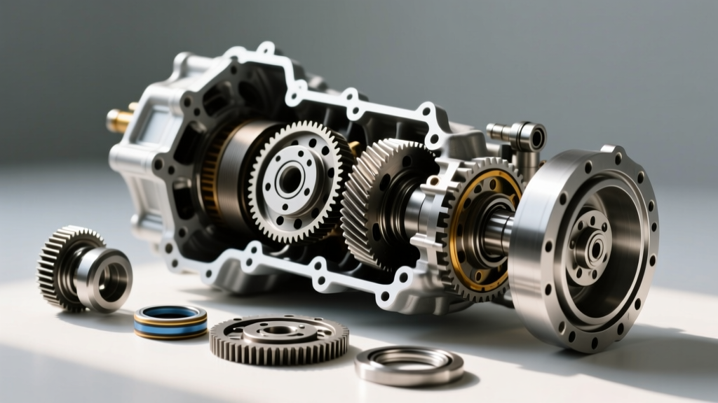
The GM 4L60E remains one of the most widely produced and rebuilt rear-wheel-drive automatic transmissions in automotive history. Whether you are refreshing a daily driver or building a reinforced unit for a high-torque application, executing proper transmission bench build procedures is the difference between a reliable drivetrain and a catastrophic failure. When enthusiasts and professionals begin sourcing a 4 l 60 e transmission rebuild kit, they are often overwhelmed by the sheer volume of frictions, steels, and gaskets included. This comprehensive guide breaks down the exact bench assembly sequence, critical clearance specifications, and torque values required to build a bulletproof 4L60E in a modern 2026 workshop environment.
Before touching a single component, it is vital to understand that a bench build is not merely about swapping old parts for new ones. It is a process of verifying geometries, measuring endplay, and ensuring hydraulic integrity. According to industry data from Transmission Digest, over 65% of premature transmission failures post-rebuild are traced back to improper endplay settings and contaminated valve bodies during the bench assembly phase.
Phase 1: Pre-Bench Preparation and Kit Inventory
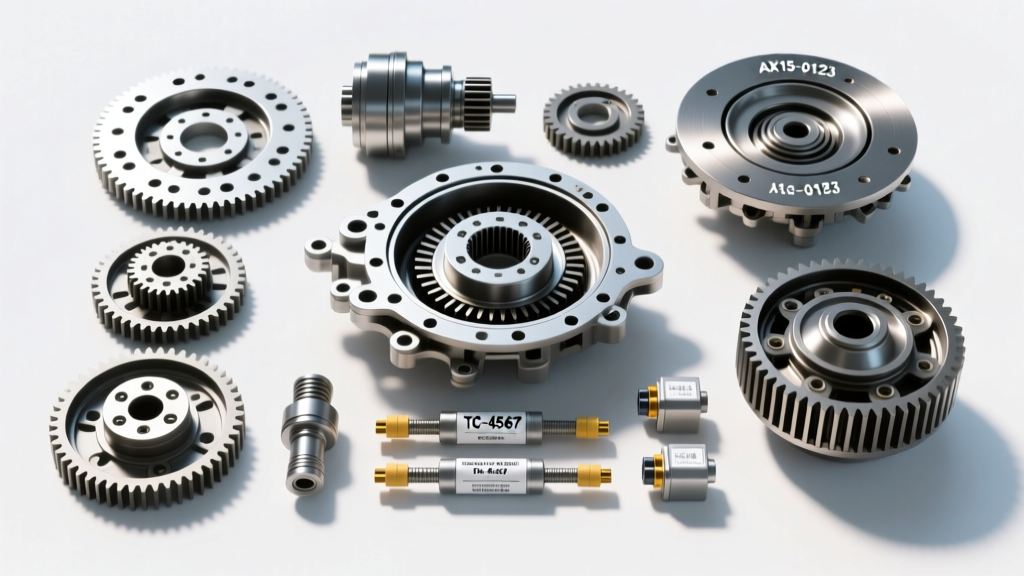
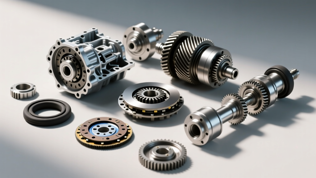
A premium master overhaul kit typically includes all paper gaskets, rubber lip seals, O-rings, metal-clad seals, and bonding seals. However, a true high-performance build requires upgrading the friction materials. We highly recommend utilizing a Raybestos GPZ friction module. The GPZ lineup offers superior heat dissipation and increased torque capacity, which is critical for the notoriously weak 3-4 clutch pack.
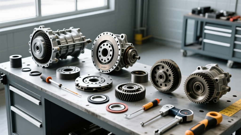
Critical Tooling Requirements
- Dial indicator with magnetic base (0.001-inch resolution)
- Feeler gauge set (metric and imperial)
- Clutch pack compressor tool (specific to 4L60E input drum)
- Inch-pound and foot-pound torque wrenches (calibrated within the last 12 months)
- Assembly lube (petroleum-based, non-water-soluble)
Phase 2: Pump and Stator Support Assembly
The front pump is the heart of the transmission. If the pump fails on the bench or upon initial startup, the entire unit will starve for pressure and burn out the clutches in seconds. Begin by inspecting the pump housing for scoring. If the crescent gear pockets show visible wear, the pump body must be replaced.
Install the new stator support bushing and inner pump gear. When assembling the pump gears, you must verify the gear-to-housing clearance. Using a straight edge and feeler gauge, measure the clearance between the top of the gears and the pump cover. The factory specification is 0.0015 to 0.004 inches. If clearance exceeds 0.005 inches, volumetric efficiency drops, leading to low line pressure at idle. Apply a generous coat of assembly lube to the gears, install the new pump slide seal rings, and torque the pump cover bolts to 18 ft-lbs (25 Nm) in a crisscross pattern.
Phase 3: The Infamous 3-4 Clutch Pack and Input Drum
The 3-4 clutch pack is the most common failure point in the 4L60E platform. The factory setup often suffers from inadequate apply area and poor heat dissipation during the 2-3 shift. To combat this, modern bench builds utilize a reinforced BorgWarner input drum and a Raybestos GPZ friction set.
Clutch Pack Assembly Procedure
Start by installing the 3-4 apply piston into the input drum. Ensure the inner and outer lip seals are properly seated and lubricated. Install the heavy-duty return spring assembly. Next, alternate the installation of the GPZ friction discs and the Kolene-coated steel separator plates. The sequence typically begins and ends with a friction disc, but always verify with the specific instruction sheet included in your kit, as aftermarket drum capacities can vary.
Once the pack is assembled, install the pressure plate and the snap ring. This is where precision is mandatory. You must measure the clutch pack clearance using a feeler gauge between the top friction disc and the pressure plate. The target clearance for the 3-4 clutch pack is 0.030 to 0.050 inches. If the clearance is too tight, the clutches will drag and burn; if it is too wide, you will experience delayed, harsh shifts. Adjust the clearance by swapping the selective pressure plate (available in varying thicknesses from 0.270 to 0.330 inches) until the spec is perfectly met.
Phase 4: Reaction Carrier and Low/Reverse Clutch
Move to the rear of the case to assemble the low/reverse clutch pack and the reaction carrier. The low/reverse clutch applies in first gear and reverse. Install the waved cushion ring first to soften the engagement, followed by the frictions and steels. Target clearance for the low/reverse pack is slightly wider, typically 0.040 to 0.070 inches, to account for the thermal expansion of the thick steels used in this section.
When installing the reaction carrier into the case, ensure the sun gear meshes smoothly with the internal pinions. Do not force the carrier, as misalignment will chip the planetary gears. Lubricate the carrier thrust bearing with petroleum jelly to hold it in place during the main case integration.
Phase 5: Endplay Verification (The Make-or-Break Step)
Setting the transmission endplay is arguably the most critical step in any transmission bench build procedure. Endplay is the total amount of axial movement of the internal gear train. Too much endplay results in violent banging during gear changes and rapid thrust washer wear. Too little endplay causes the gear train to bind, generating massive amounts of heat and parasitic drag.
Measuring Endplay on the Bench
- Mount the dial indicator to the transmission bellhousing area, with the plunger resting squarely on the input shaft.
- Push the input shaft fully inward (toward the torque converter) and zero the dial indicator.
- Pull the input shaft fully outward (toward the output shaft) and read the measurement.
The acceptable endplay specification for the 4L60E is between 0.010 and 0.024 inches. If your measurement falls outside this window, you must remove the input drum and swap the selective thrust washer located between the pump stator and the input drum. These washers are available in thicknesses ranging from 0.100 to 0.160 inches. Re-measure until the endplay sits comfortably around 0.015 inches.
Phase 6: Valve Body Upgrades and Extension Housing
The 4L60E valve body is highly susceptible to bore wear, particularly in the torque converter clutch (TCC) PWM valve and the line pressure boost valve. Simply reinstalling a worn valve body with new paper gaskets will result in TCC shudder and slipping under load. We strongly advise installing a Sonnax Zip Kit or a complete reamer-and-sleeve kit to restore hydraulic integrity to the valve body castings.
When bolting the valve body to the main case, use new torque-to-yield bolts or apply a medium-strength thread locker to standard bolts. Torque the valve body to case bolts to 97 in-lbs (11 Nm). Over-torquing these bolts will distort the valve body separator plate and cause cross-leaking between hydraulic circuits. Finally, install the extension housing with a new output shaft seal and metal-clad gasket, torquing the housing bolts to 27 ft-lbs (37 Nm).
4L60E Bench Build Cost and Tooling Breakdown
Understanding the financial investment of a proper bench build is essential for both DIY mechanics and professional shops. Below is a realistic cost breakdown for a high-quality 4L60E rebuild in 2026, excluding the core transmission and vehicle removal labor.
| Component / Service | Estimated Cost (USD) | Notes |
|---|---|---|
| Master Rebuild Kit (Seals, Gaskets, Rings) | $120 - $180 | Includes all paper and rubber components |
| Raybestos GPZ Friction Module | $180 - $250 | High-performance clutch disc upgrade |
| Kolene Steel Separator Plates | $90 - $130 | Prevents warping under high heat |
| Sonnax Valve Body Zip Kit | $110 - $150 | Corrects TCC and boost valve bore wear |
| Bushings and Thrust Washers | $60 - $90 | Critical for endplay and gear alignment |
| Dexron VI Transmission Fluid (12 Qts) | $70 - $100 | Required for modern GM applications |
| Specialty Tools (Compressor, Dial Indicator) | $80 - $150 | One-time purchase for DIY builders |
| Total Estimated Parts Cost | $710 - $1,050 | Varies based on hard part replacements |
Final Bench Testing and Fluid Priming
Before the transmission leaves the bench, manually rotate the input shaft to ensure smooth rotation through all planetary gear sets. There should be no binding or metallic scraping sounds. Install the torque converter, ensuring it fully seats into the pump drive gear. You must verify that the converter is seated at least 1/8th of an inch below the bellhousing mating surface. Failure to fully seat the converter will result in the converter crushing the pump gears against the stator upon bellhousing bolt tightening, destroying the transmission instantly.
For further technical specifications and advanced hydraulic circuit diagrams, professionals frequently reference the engineering archives available at Raybestos Powertrain. By adhering strictly to these bench build procedures, verifying every clearance, and utilizing upgraded components, your 4L60E will deliver reliable, firm shifts and exceptional longevity on the road.