Defining the "Automatic Gear Clutch" in Modern Drivetrains
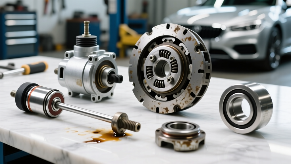
When technicians and enthusiasts refer to an automatic gear clutch, they are generally addressing two distinct but interrelated friction systems within an automatic transmission: the internal wet multi-plate clutch packs that facilitate gear ratio changes, and the Torque Converter Clutch (TCC) that locks the engine to the transmission input shaft for 1:1 efficiency. In modern 8-speed and 10-speed platforms—such as the ZF 8HP series and the GM 8L90/10L90 families—these friction elements operate under extreme thermal and hydraulic stress. A failure in either system results in slipping, harsh engagements, or complete loss of propulsion.
This technical deep-dive provides a comprehensive automatic gear clutch inspection checklist. Whether you are diagnosing a shuddering TCC in a GM 6L80 or measuring clutch pack end-play in a ZF 8HP45, this guide outlines the precise diagnostic protocols, dimensional specifications, and hydraulic benchmarks required for a definitive repair.
Phase 1: Pre-Teardown Diagnostics & Hydraulic Baseline
Before unbolting the bellhousing, you must establish a hydraulic and electronic baseline. Internal clutch pack failures often mimic valve body or solenoid failures. Relying on the Automatic Transmission Rebuilders Association (ATRA) diagnostic frameworks, begin with these in-vehicle tests:
- TCC Slip RPM Monitoring: Using a bidirectional scan tool, monitor the TCC Slip Speed PID while cruising in top gear at a steady throttle (typically 55-65 mph). A healthy system should show 0 to 10 RPM of slip. Consistent slip greater than 25 RPM under steady-state load indicates a failing TCC friction lining, a leaking turbine shaft seal, or a worn TCC regulator valve.
- Line Pressure Verification: Connect a 0-300 PSI mechanical transmission pressure gauge to the main line tap. For a GM 6L80, base pressure at idle in Reverse should be approximately 55-75 PSI, spiking to over 250 PSI during a stall test. If pressure is low, the internal clutch packs will slip and burn prematurely due to insufficient apply force.
- Adaptive Pressure Reset: If you suspect clutch wear, check the Transmission Control Module (TCM) adaptive pressure tables. If the TCM has maxed out the adaptive pressure multiplier (e.g., adding 30+ PSI to base line pressure) to maintain shift times, the physical friction material is severely degraded.
Phase 2: Bench Teardown & Air-Testing Protocol
Once the transmission is on the bench, do not immediately rip out the snap rings. The most critical step in the automatic gear clutch inspection checklist is the air-check procedure. This verifies piston seal integrity and clutch apply travel before disassembly.
The Air-Check Procedure
Using a rubber-tipped blowgun regulated to 30-45 PSI, apply compressed air directly to the clutch feed holes located in the transmission case or pump stator.
- Audible & Visual Confirmation: You should hear a distinct, solid "thud" as the apply piston moves and seats against the clutch pack. A hissing sound indicates a cut piston lip seal, a scored cylinder bore, or a leaking O-ring on the stator support.
- Dial Indicator Measurement: Mount a magnetic dial indicator on the transmission case with the plunger resting on the pressure plate. Apply air and record the travel distance. This travel distance represents your clutch pack clearance. Compare this against the manufacturer specifications detailed in Phase 3.
- Release Check: When air pressure is removed, the return spring must immediately push the piston back. Slow retraction indicates a binding piston, a swollen lip seal (often caused by incorrect aftermarket fluids), or a collapsed return spring.
Phase 3: Dimensional Inspection & Clearance Specifications
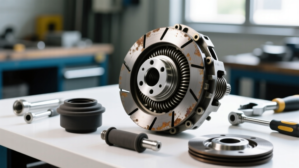
After removing the snap rings and extracting the friction and steel plates, perform a meticulous dimensional inspection. Friction plates should be measured with a micrometer. A standard new friction plate is typically between 1.50mm and 2.00mm thick. If the friction material is worn down by more than 0.20mm per plate, or if the paper/carbon lining shows signs of glazing, flaking, or heat spotting (bluish discoloration on the mating steel plates), the entire pack must be replaced.
Below is a reference table for target clearances on popular modern platforms. Always verify with the specific OEM service manual, as clearances vary by exact sub-model and year.
| Transmission Model | Clutch Pack / Element | Target Clearance (New) | Maximum Wear Limit |
|---|---|---|---|
| ZF 8HP45 / 8HP70 | Clutch A (1-2-3-4) | 0.60 - 0.90 mm | 1.20 mm |
| ZF 8HP45 / 8HP70 | Clutch E (R-1-2-3) | 0.40 - 0.70 mm | 1.00 mm |
| GM 8L90 | Clutch 1-2-3-4 | 0.020" - 0.040" | 0.065" |
| GM 6L80 | 3-5-R Clutch Pack | 0.040" - 0.070" | 0.095" |
Expert Tip: When measuring clearance with feeler gauges, never measure in just one spot. Always measure at three or four equidistant points around the circumference of the pressure plate. A variance of more than 0.15mm between points indicates a warped pressure plate, a bowed snap ring, or a distorted clutch drum, which will cause localized hot-spotting and rapid clutch failure upon reassembly.
Phase 4: Torque Converter Clutch (TCC) & Valve Body Inspection
The TCC is the most common culprit behind highway-speed shudder and diagnostic trouble codes like P0741 (TCC System Stuck Off). Because the TCC is sealed inside the torque converter, physical inspection requires cutting the converter open on a lathe—a job usually outsourced to specialized torque converter remanufacturers. However, the root cause of TCC failure almost always lies in the valve body.
According to Sonnax Technical Resources, continuous micro-slippage of the TCC generates immense particulate debris. This debris circulates through the cooler and becomes trapped in the TCC regulator valve bore, causing the valve to stick and resulting in uncontrolled apply pressure.
Valve Body Checklist:
- Visual Bore Inspection: Drop the TCC regulator valve and inspect the aluminum bore for scoring. If light passes between the valve spool and the bore wall, the bore is worn.
- Vacuum Testing: Use a vacuum test stand to check the TCC control valve. A reading below 18 inches of Hg indicates severe hydraulic leakage.
- Corrective Action: If wear is detected, install an oversized TCC regulator valve kit (e.g., Sonnax part number 95740-09K for the GM 6L80) which requires reaming the bore to accept the larger, anodized valve spool and integrated O-rings.
Phase 5: Reassembly Protocols, Torque Specs, and Fluid Selection
Reassembling an automatic gear clutch pack requires strict adherence to cleanliness and torque specifications. A single stray lint fiber from a shop towel can block a microscopic feed orifice in the clutch drum, leading to a delayed engagement and burnt clutches within 50 miles.
Critical Reassembly Steps:
- Pre-Soaking Frictions: Submerge all new paper or carbon-based friction plates in the exact OEM-approved transmission fluid for a minimum of 2 hours prior to installation. Installing dry frictions will cause immediate glazing upon first apply.
- Seal Lubrication: Lubricate all piston lip seals and stator O-rings with a dedicated assembly gel (like Sonnax Slippery Stick) or the target transmission fluid. Never use petroleum jelly, which can melt and block valve body screens.
- Fastener Torque Specs: When reinstalling the oil pump and bellhousing, precise torque is vital to prevent case distortion that binds the clutch drums. For the GM 6L80/8L90 family, the pump-to-case bolts must be torqued to 11 Nm (97 lb-in) in a star pattern. The torque converter-to-flexplate bolts typically require 46 Nm (34 lb-ft) with a medium-strength threadlocker.
Fluid Selection: The Lifeblood of the Clutch Pack
Modern automatic gear clutches are engineered around the specific friction modifiers of their designated fluids. Using the wrong fluid will alter the coefficient of friction, leading to harsh shifts or slip. For the ZF 8HP platform, ZF Aftermarket strictly mandates the use of ZF LifeguardFluid 8 (or the updated LifeguardFluid 8+ for newer models). For GM's 8-speed and 10-speed units, Dexron ULV (Ultra Low Viscosity) is mandatory. These fluids retail between $12 and $25 per quart, and a complete dry-fill capacity can range from 8.5 to 11.5 liters, making fluid cost a significant line item in the repair estimate.
Summary: The Economics of Proper Inspection
Skipping steps on the automatic gear clutch inspection checklist is a false economy. A master rebuild kit for a ZF 8HP or GM 8L90, including updated friction packs, steel plates, and piston seals, typically costs between $450 and $850. A remanufactured torque converter adds another $400 to $700. However, failing to identify a worn valve body bore or ignoring out-of-spec clutch clearances will result in a comeback. In the transmission repair industry, a comeback costs not only the $1,500+ in R&R labor but also your shop's reputation. By rigorously applying hydraulic baselines, air-testing, and precise dimensional measurements, you ensure the automatic gear clutch system operates flawlessly for another 150,000 miles.