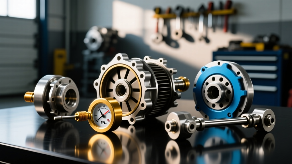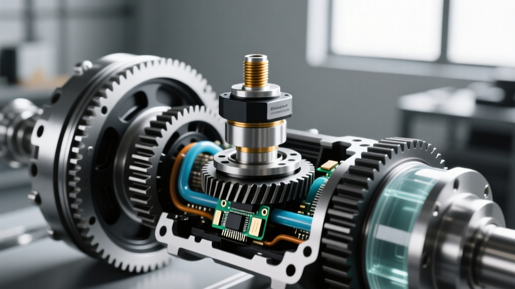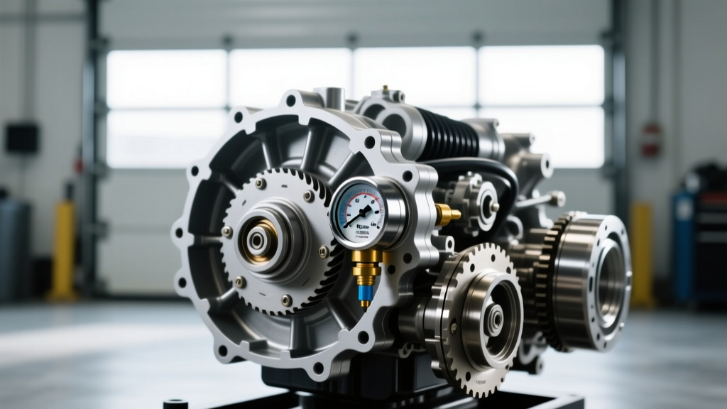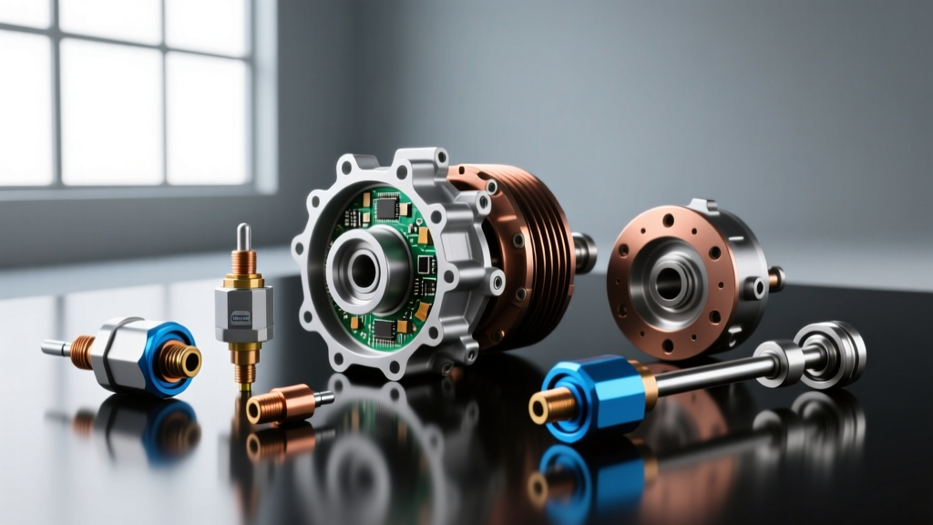
The Nervous System of Your Transmission: Pressure vs. Heat
Welcome to the intersection of modern transmission diagnostics. If you are new to automotive repair, the alphabet soup of sensors under your vehicle can easily cause confusion. Two common culprits for erratic shifting, harsh engagements, and limp-mode activation are differential pressure sensors and the transmission fluid temperature (TFT) sensor. While they monitor entirely different physical properties, their failure symptoms frequently overlap, leading to misdiagnosis and wasted money.
In this beginner-friendly explainer, we will demystify these components. We will focus deeply on resolving transmission temperature sensor issues, distinguish them from differential pressure sensor faults, and provide the exact data, part numbers, and torque specs needed for real-world repairs on popular units like the GM 6L80, Ford 6R80, and ZF 8HP. As of 2026, with the integration of advanced 10-speed and hybrid transmissions, understanding these baseline electronic principles is more critical than ever.
Understanding the Core Differences
Before grabbing a multimeter, you must understand what the Transmission Control Module (TCM) is actually looking at. The TCM relies on a network of inputs to determine shift timing, line pressure, and torque converter clutch (TCC) lockup.
What is a Differential Pressure Sensor?
A differential pressure sensor measures the difference in pressure between two points. In automotive applications, these are most commonly found in diesel emissions systems (measuring the pressure drop across a Diesel Particulate Filter) or in specific advanced hydraulic circuits to monitor filter restriction or clutch apply pressure. If a transmission-related differential pressure sensor fails, the TCM or PCM cannot determine if a fluid filter is clogged or if a specific clutch volume is leaking, usually resulting in delayed shifts or filter-clogging warnings.
What is a Transmission Fluid Temperature (TFT) Sensor?
The TFT sensor is almost always a Negative Temperature Coefficient (NTC) thermistor. This means its electrical resistance decreases as the fluid gets hotter. The TCM sends a 5-volt reference signal to the sensor; as the fluid heats up and resistance drops, the signal voltage drops. The TCM uses this data to adjust shift firmness (cold fluid requires higher line pressure to prevent clutch slip) and to trigger thermal protection modes if the fluid overheats.
Diagnostic Comparison Chart
Use this table to quickly differentiate between the two sensor types when scanning for faults.
| Feature | TFT Sensor (Temperature) | Differential Pressure Sensor |
|---|---|---|
| Primary Function | Monitors fluid heat for shift scheduling & cooling | Monitors pressure drop across filters or clutch circuits |
| Typical Location | Valve body, TEHCM, or Solenoid Body | Emissions system, specialized hydraulic valve bodies |
| Common DTCs | P0711, P0712, P0713 | P2453, P2454, or specific OEM hydraulic codes |
| Primary Symptom | Harsh shifts when cold, limp mode, TCC lockup disabled | Filter restriction warnings, delayed engagements |
Why Temperature Dictates Shift Quality
Beginners often wonder why a bad temperature sensor causes the car to shift like it has been rear-ended. Transmission fluid (ATF) changes viscosity drastically with temperature. If the TFT sensor circuit breaks (an open circuit), the TCM sees infinite resistance and defaults to a fail-safe reading, often -40°F (-40°C). Believing the fluid is freezing, the TCM commands maximum line pressure to prevent clutch slip. The result? Bone-jarring, tire-chirping shifts that feel like a mechanical failure, even though the internal hard parts are perfectly fine.
Conversely, if the sensor shorts out, the TCM might read 300°F (149°C). To protect the clutches from burning up, the TCM will immediately command limp mode, locking the transmission in a single gear (usually 3rd or 4th) and disabling overdrive and torque converter lockup. According to diagnostic databases like OBD-Codes, a P0711 (TFT Sensor Circuit Range/Performance) is one of the most frequently misdiagnosed codes because technicians assume the transmission is mechanically binding, rather than electronically confused.
Step-by-Step Diagnosis for Beginners
Do not throw parts at the vehicle. Follow this proven diagnostic workflow to confirm transmission temperature sensor issues.
Step 1: Scan Tool PID Analysis (The Cold Morning Test)
Leave the vehicle outside overnight. First thing in the morning, connect a bi-directional OBD2 scan tool and look at the Live Data PIDs. Compare the TFT (Transmission Fluid Temp) to the ECT (Engine Coolant Temp) and IAT (Intake Air Temp). Because the car has been sitting, all three sensors should read within 5°F to 10°F of the ambient outdoor temperature. If the ECT and IAT read 60°F, but the TFT reads -40°F or 280°F, you have instantly confirmed a circuit or sensor failure without turning a single wrench.
Step 2: Multimeter Testing the Thermistor
If you have access to the transmission pan, you can test the thermistor directly. Set your multimeter to Ohms (Ω). Backprobe the sensor connector or test the pins on the component itself. Compare your readings to the manufacturer's resistance chart. A typical GM/Chrysler NTC thermistor follows this general curve:
- 32°F (0°C): ~28,000 to 32,000 Ohms
- 70°F (21°C): ~9,000 to 11,000 Ohms
- 212°F (100°C): ~1,200 to 1,500 Ohms
If your multimeter reads 'OL' (Open Loop), the internal thermistor wire has snapped. If it reads near 0 Ohms, it is shorted.
Real-World Repair Scenarios: Costs, Parts, and Torque Specs
Transmission temperature sensor issues vary wildly in repair complexity depending on the transmission model. Here is what you need to know for the most common units on the road today.
Scenario A: GM 6L80 / 6L90 (TEHCM Failures)
In the GM 6-speed automatic family, the TFT sensor is not a standalone part. It is permanently integrated into the TEHCM (Transmission Electro-Hydraulic Control Module), which is the combined valve body and TCM unit located inside the transmission pan.
The Fix: You must replace the entire TEHCM or perform advanced micro-soldering to bypass the internal thermistor trace.
Part Number: AC Delco 24253109 (Verify with your VIN).
Cost: $450 to $650 for the part.
Torque Spec: When reinstalling the TEHCM to the valve body separator plate, the bolts must be torqued to exactly 8 Nm (71 lb-in). Over-tightening will warp the aluminum valve body and cause cross-leak hydraulic failures.
Scenario B: ZF 8HP (BMW, Chrysler, Ford 10-Speed)
The legendary ZF 8HP uses a mechatronic unit that houses the TCM, solenoids, and temperature sensor. However, a common beginner trap is replacing the $1,200 mechatronic unit when the real issue is a degraded mechatronic sealing sleeve. This plastic sleeve connects the transmission case to the mechatronic unit. When it degrades, it leaks fluid onto the external electrical pins, causing signal corruption that mimics a TFT sensor failure. As detailed by Sonnax Technical Resources, replacing the $40 sealing sleeve and cleaning the pins with contact cleaner resolves the issue 80% of the time.
Torque Spec: ZF mechatronic to transmission case bolts: 10 Nm (89 lb-in).
Scenario C: Ford 6R80 (Solenoid Body Integration)
Similar to the GM setup, the TFT sensor in the Ford 6R80 is integrated into the solenoid body assembly. If the sensor fails, the entire solenoid strap and body must be replaced.
Part Number: Ford BL3Z-7G101-A (Solenoid Body Assembly).
Cost: $220 to $280.
Fluid Note: The 6R80 requires exactly 11.2 quarts of Mercon LV for a pan-drop and solenoid body replacement. Do not use generic 'multi-vehicle' ATF, as the friction modifiers will cause shudder.
When to Call a Professional
While reading PIDs and testing resistance are well within the capabilities of a dedicated DIYer, removing a valve body or TEHCM requires a sterile environment. A single human hair or grain of sand trapped between a valve body and separator plate will cause a pressure leak, leading to burnt clutches within 100 miles. Furthermore, many modern TEHCM and Mechatronic units require proprietary J2534 pass-through programming or 'relearn' procedures via OEM software (like GM's GDS2 or Ford's IDS) to match the new sensor's calibration to the TCM.
Summary
Understanding the distinction between differential pressure sensors and transmission temperature sensor issues is the hallmark of a smart diagnostician. By relying on cold-morning PID comparisons, verifying thermistor resistance curves, and respecting the precise torque specs of modern valve bodies, you can save yourself thousands of dollars in misdiagnosed transmission replacements. Always let the data guide your wrench, not your assumptions.