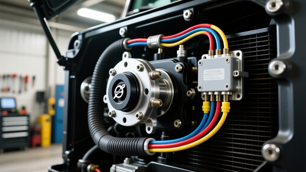
The Critical Role of Transmission Fluid Temperature (TFT) Data
In modern automotive engineering, the Transmission Control Module (TCM) relies heavily on precise thermal data to dictate shift scheduling, line pressure, and torque converter clutch (TCC) apply rates. When the transmission fluid temperature (TFT) sensor fails or provides erratic data, the TCM defaults to a fail-safe mode, resulting in harsh shifts, locked gears, or complete limp-home activation. Understanding the exact transmission temp sensor location and mastering the electrical troubleshooting process is essential for any preventive maintenance strategy. This guide dives deep into the circuitry, diagnostic trouble codes (DTCs like P0711, P0712, and P0713), and model-specific architectures of modern automatic transmissions.
Pinpointing the Transmission Temp Sensor Location by Model
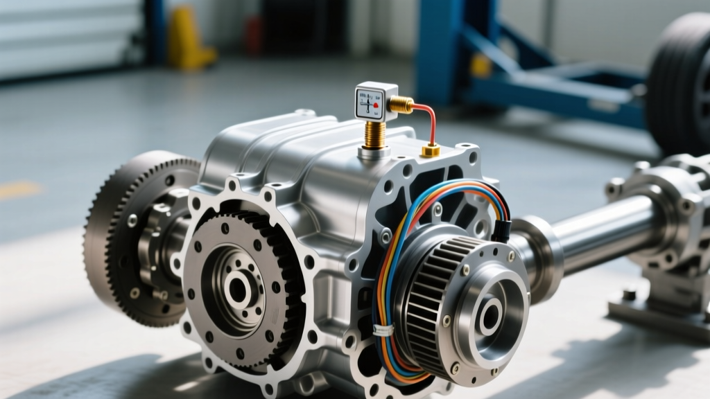
The physical transmission temp sensor location varies drastically depending on the manufacturer and the generation of the transmission. In older 4-speed units, the sensor was often a standalone, externally threaded component. In modern 6, 8, and 10-speed transmissions, the sensor is almost exclusively integrated into the mechatronic unit or valve body assembly.
GM 6L80 and 6L90 (TEHCM Architecture)
For General Motors' ubiquitous 6L80 and 6L90 transmissions, the temp sensor is not a standalone serviceable part. It is permanently molded into the Transmission Electro-Hydraulic Control Module (TEHCM), located inside the transmission pan. If the sensor's internal thermistor fails, the entire TEHCM assembly (Part # 24254035 or vehicle-specific equivalent) must be replaced and reprogrammed using GDS2 software.
ZF 8HP (Mechatronic Integration)
In the ZF 8HP series (found in BMW, Audi, Chrysler, and Ford applications), the sensor is soldered directly onto the printed circuit board (PCB) of the Mechatronic unit. According to ZF Aftermarket technical bulletins, thermal stress and conductive clutch material in degraded fluid are the primary culprits for PCB-level sensor failure. Replacement requires dropping the valve body and replacing the entire mechatronic assembly.
Ford 6R80 and 10R80 (Solenoid Body)
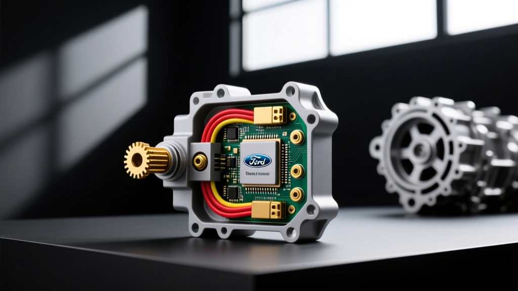
Ford's 6R80 and 10R80 units house the TFT sensor within the internal solenoid body/lead frame assembly. While slightly more accessible than the ZF mechatronic, replacing it still requires pan removal, valve body extraction, and careful handling of the fragile ribbon cables connecting the solenoid body to the external harness.
Legacy External Sensors (GM 4L60E, Toyota A750E)
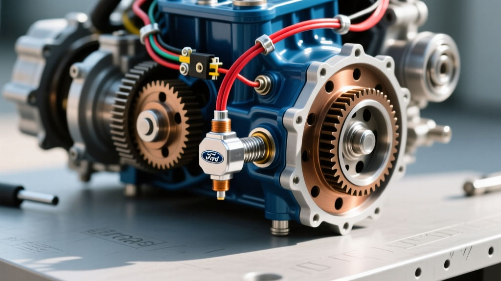
For older or heavy-duty applications utilizing an external threaded sensor, the transmission temp sensor location is typically on the side of the transmission case or threaded directly into the valve body casting, accessible from under the pan. These require a specific torque spec—usually 15 to 20 Nm (11-15 lb-ft)—and a high-temperature thread sealant to prevent fluid leaks.
| Transmission Model | Sensor Location | Serviceability | Approx. Part Cost (OEM) |
|---|---|---|---|
| GM 6L80 / 6L90 | Internal TEHCM | Replace entire TEHCM | $650 - $950 |
| ZF 8HP (BMW/Audi) | Mechatronic PCB | Replace Mechatronic | $1,200 - $2,500 |
| Ford 6R80 | Solenoid Body/Lead Frame | Replace Solenoid Body | $350 - $550 |
| GM 4L60E (External) | Threaded into Case/Pan | Standalone Replacement | $25 - $60 |
| Chrysler NAG1 (722.6) | Conductor Plate | Replace Conductor Plate | $180 - $280 |
Step-by-Step Electrical Troubleshooting for P0711, P0712, and P0713
Before ordering expensive mechatronic units, a rigorous electrical diagnostic protocol must be followed. The TCM monitors the TFT sensor circuit for plausibility (P0711), low voltage/short to ground (P0712), and high voltage/open circuit (P0713). As outlined by SAE International diagnostic frameworks, isolating the fault to either the sensor, the wiring harness, or the TCM itself requires a systematic approach.
1. Cold-Start PID Cross-Referencing
Connect a bi-directional scan tool and monitor the Transmission Fluid Temperature (TFT) PID alongside the Engine Coolant Temperature (ECT) and Intake Air Temperature (IAT) PIDs. After the vehicle has sat overnight (cold soak), all three sensors should read within 5°F to 10°F of each other and the ambient outside temperature. If the TFT reads -40°F or 300°F immediately on a cold start, you have a hard electrical fault (open or short).
2. The 5-Volt Reference and Signal Return Test
Most modern TFT sensors are Negative Temperature Coefficient (NTC) thermistors operating on a 5-volt reference circuit.
- Step A: Disconnect the main transmission harness connector at the TCM or the external case connector.
- Step B: With the ignition ON, engine OFF (KOEO), use a digital multimeter (DMM) to probe the 5V reference wire. You should read exactly 4.8V to 5.1V. If it reads 0V, suspect a shorted sensor pulling the reference down, or a faulty TCM.
- Step C: Check the signal return (ground) circuit for continuity to the chassis ground. Resistance should be less than 0.5 ohms.
3. NTC Thermistor Resistance Mapping
To test the sensor itself, you must measure its resistance across the sensor pins and compare it to the manufacturer's thermistor curve. Because it is an NTC thermistor, resistance drops as temperature rises. Below is a standard baseline chart for most GM and Ford NTC transmission temp sensors:
- 20°C (68°F): ~2.5 kΩ (2,500 Ohms)
- 50°C (122°F): ~0.85 kΩ (850 Ohms)
- 80°C (176°F): ~0.32 kΩ (320 Ohms)
- 120°C (248°F): ~0.09 kΩ (90 Ohms)
If your multimeter reads 'OL' (Out of Limits/Open) or near 0 Ohms (Shorted) at room temperature, the internal sensor epoxy has failed, confirming the need for component replacement.
Preventive Maintenance: Protecting the Sensor Circuit
Electrical failures in the transmission are rarely isolated events; they are often symptoms of neglected preventive maintenance. According to industry analysis from Transmission Digest, the leading cause of premature TFT sensor failure is fluid degradation.
Combating Fluid Acidity and Conductive Sludge
As automatic transmission fluid (ATF) ages, it oxidizes and becomes acidic. This acidic environment eats away at the protective epoxy coating the thermistor and the solder joints on the mechatronic PCB. Furthermore, worn clutch packs shed metallic and friction material into the fluid, creating a conductive sludge that can bridge the gaps between the sensor's signal and ground traces, causing erratic P0711 plausibility codes. Preventive Action: Perform fluid drain-and-fills every 40,000 to 60,000 miles using strictly OEM-approved fluids (e.g., Dexron VI for GM, ZF Lifeguard 8 for ZF units). Avoid generic 'multi-vehicle' fluids that lack the specific dielectric properties required by modern solenoid bodies.
Connector and Harness Preservation
The external transmission harness connector is highly susceptible to moisture intrusion and road salt corrosion. Preventive Action: During every major service, disconnect the main transmission pass-through connector. Clean the pins with electrical contact cleaner and apply a high-quality dielectric grease (such as Permatex 22058) to prevent moisture ingress. Additionally, inspect the harness where it routes near the exhaust or bellhousing; heat shielding and split-loom tubing should be replaced if brittle or melted.
Real-World Repair Costs and Labor Times
Understanding the financial impact of these repairs helps technicians and fleet managers justify strict preventive maintenance schedules.
- External Sensor Replacement (e.g., 4L60E): 0.5 hours labor + $40 part. Total: ~$100 - $150.
- TEHCM Replacement (GM 6L80): 2.5 hours labor + $800 part + GDS2 Programming. Total: ~$1,200 - $1,600.
- Mechatronic Replacement (ZF 8HP): 6.0 hours labor + $1,800 part + Adaptation Programming. Total: ~$2,800 - $4,500.