The Magic of Fluid Coupling: An Introduction
Unlike a manual transmission that relies on a mechanical friction disc and pressure plate to connect the engine to the gearbox, an automatic transmission uses a fluid coupling device known as a torque converter. If you have ever wondered how your car can come to a complete stop at a red light while the engine is still running and in gear, the torque converter is the answer. To truly understand transmission diagnostics and failure modes, you must first understand the hydrodynamic principles at play. In this beginner-friendly explainer, we will break down the internal operation of the torque converter, using engineering standards and remanufacturing benchmarks often cited by industry leaders like ATRA and top-tier builders such as Quality Torque Converters Inc.
Inside the Shell: The Core Components
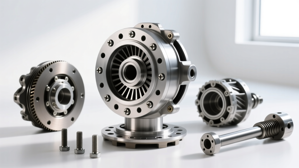
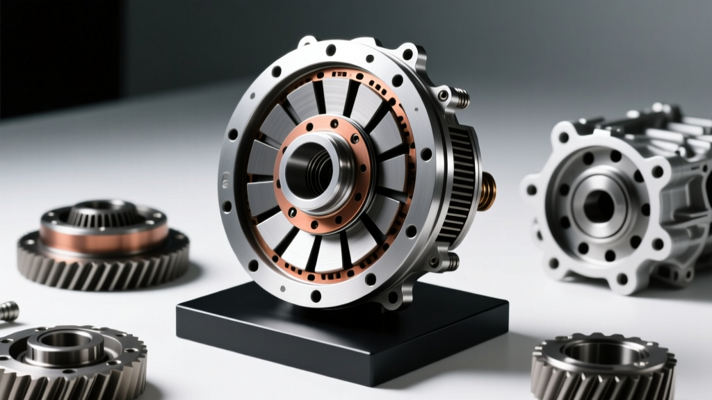
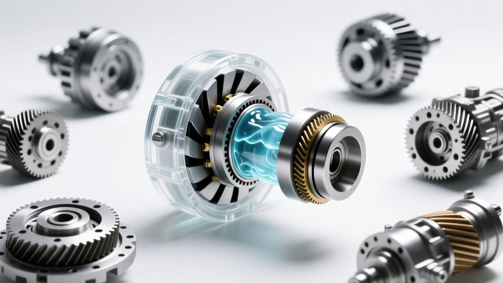
A torque converter is essentially a sealed, donut-shaped housing filled with automatic transmission fluid (ATF). It is bolted directly to the engine's flexplate, meaning it spins whenever the engine is running. Inside this shell, there are three primary rotating elements:
- The Impeller (Pump): This is welded directly to the outer shell of the converter. As the engine spins the shell, the impeller's internal fins grab the ATF and fling it outward using centrifugal force.
- The Turbine: Positioned directly opposite the impeller, the turbine is splined to the transmission's input shaft. The fluid thrown by the impeller strikes the turbine's fins, causing it to spin and ultimately drive the transmission gears.
- The Stator: Sitting in the center between the impeller and turbine, the stator is mounted on a one-way clutch (sprag). Its job is to redirect the fluid returning from the turbine back into the impeller, which creates torque multiplication.
Fluid Coupling Phase vs. Mechanical Lockup
Modern torque converters operate in two distinct phases. Understanding the transition between these phases is critical for diagnosing common drivability complaints, such as highway shudder or RPM flaring.
| Operating Phase | Mechanism | Typical Driving Scenario | Efficiency |
|---|---|---|---|
| Fluid Coupling | Power transferred entirely via ATF movement between impeller and turbine. | Accelerating from a stop, heavy towing, low-speed maneuvering. | 85% - 92% (Slip generates heat) |
| TCC Lockup | Friction clutch applies, mechanically locking the turbine to the converter cover. | Cruising at steady highway speeds (usually 40+ MPH). | ~99% (Near 1:1 mechanical link) |
The Torque Converter Clutch (TCC) is a vital emissions and fuel economy device. When the Powertrain Control Module (PCM) commands the TCC solenoid, hydraulic pressure (typically between 110-140 PSI) forces a friction-lined piston against the front cover of the converter. This eliminates slip, dropping transmission fluid temperatures by up to 30°F and improving highway fuel economy by 5-8%.
Understanding Stall Speed and Torque Multiplication
One of the most misunderstood concepts in drivetrain dynamics is 'stall speed.' Stall speed is defined as the maximum RPM the engine can achieve with the transmission in gear and the output shaft held completely stationary (e.g., holding the brake pedal to the floor while matting the throttle).
For a stock GM 4L60E, the factory stall speed is typically around 1,600 to 1,800 RPM. During this phase, the stator remains locked by its sprag clutch. Because the stator redirects fluid to hit the impeller on the 'helping' side of its fins, the converter can multiply engine torque by a ratio of up to 2.2:1 or 2.5:1. This is why a vehicle with 300 lb-ft of engine torque can launch with over 600 lb-ft of torque at the input shaft.
Expert Diagnostic Tip: If a vehicle exhibits sluggish acceleration from a stop but shifts and cruises normally at highway speeds, the stator sprag has likely failed and is freewheeling in both directions. This destroys torque multiplication and requires immediate converter replacement.
Common TCC Symptoms: Diagnosing Shudder and Slip
Because the 'tc-symptoms' category heavily involves drivability issues, we must address Torque Converter Clutch shudder. Shudder feels like driving over a series of rumble strips and typically occurs between 35 and 55 MPH when the TCC is in a 'modulated slip' state.
Why Does TCC Shudder Happen?
Modern transmissions (like the GM 6L80 or Ford 10R80) rarely apply the TCC with a harsh, on/off binary switch. Instead, the PCM modulates the apply pressure to allow 20-40 RPM of slip, smoothing out engine vibrations. If the friction modifiers in the ATF break down due to heat or extended drain intervals, the friction material (often carbon-fiber or Kevlar-based) grabs and releases rapidly. This stick-slip phenomenon creates a 3-5 Hz harmonic vibration that resonates through the chassis.
Actionable Fixes for Shudder
- Fluid Analysis: Check for burnt smell or dark discoloration. Degraded Dexron VI or Mercon LV loses its friction-modifying properties.
- Chemical Flush: Products like BG Quick Clean for Transmissions can dissolve varnish on the TCC piston and valve body switches.
- Complete Exchange: Perform a full fluid exchange (not just a pan drop) using OEM-specified fluid. A 6L80 requires exactly 11.2 quarts for a full system refill.
- PCM Re-flash: In some late-model ZF 8HP applications, TCC shudder is caused by aggressive factory slip maps. A dealer TCM re-flash can alter the apply pressure curve.
Real-World Transmission Specifications
When sourcing a replacement or diagnosing a system, you must match the converter to the specific transmission architecture. Below is a comparison of common modern and legacy automatic transmissions and their torque converter profiles.
| Transmission Model | Converter Diameter | Typical Stock Stall | Total System Fluid Capacity | TCC Friction Type |
|---|---|---|---|---|
| GM 4L60E | 245mm / 298mm | 1,600 - 1,800 RPM | 11.2 - 12.0 Quarts | Paper / Cellulose |
| GM 6L80 / 6L90 | 300mm | 1,800 - 2,100 RPM | 11.2 Quarts | Carbon-Fiber |
| Ford 10R80 | 260mm (Z-Barrel) | 1,500 - 1,700 RPM | 13.1 Quarts | Multi-Plate Carbon |
| ZF 8HP (8-Speed) | 260mm - 300mm | 1,400 - 1,600 RPM | 9.5 - 10.5 Liters | Twin-Damper Carbon |
Rebuilding Standards: The Quality Torque Converters Inc Approach
When a torque converter fails internally—whether from a fractured turbine hub, a blown stator sprag, or contaminated friction linings—it cannot simply be drained and refilled. The unit must be cut open on a lathe, cleaned, and rebuilt. Reputable remanufacturers, such as Quality Torque Converters Inc, adhere to strict engineering tolerances to prevent catastrophic transmission failure.
Key remanufacturing steps include:
- Hub Replacement: The turbine hub (which rides on the transmission's front pump bushing) is machined and replaced if scored. A worn hub will cause front pump leaks and low line pressure.
- Dynamic Balancing: Once welded back together, the assembly is spun on a dynamic balancing machine. High-quality builders balance the converter to within 0.010 to 0.020 inch-ounces. Poor balancing causes severe input shaft vibration and premature main bearing wear.
- Pressure Testing: The sealed unit is pressurized with air (usually to 80-100 PSI) and submerged in water to check for microscopic weld leaks before shipping.
Installation Torque Specs and Best Practices
Even a perfectly rebuilt torque converter will fail if installed incorrectly. When mating the converter to the flexplate, always use new hardware. For most GM applications (4L60E, 6L80), the M10x1.5 flexplate-to-converter bolts must be torqued to 35-45 lb-ft with a medium-strength threadlocker (blue). For Ford applications (like the 10R80), the torque spec is typically lower, around 20-25 lb-ft.
Furthermore, ensure the converter is fully seated into the transmission front pump before bolting the transmission to the engine block. You should hear and feel three distinct 'clunks' as the turbine splines, stator support, and front pump gears engage. If the converter is not fully seated, tightening the bellhousing bolts will crush the front pump, resulting in immediate, catastrophic failure upon engine startup.
Conclusion
The torque converter is a marvel of hydrodynamic engineering, bridging the gap between internal combustion and automatic gear multiplication. By understanding the distinct phases of fluid coupling, the mechanics of the stator, and the hydraulic realities of the TCC, both DIY enthusiasts and professional technicians can accurately diagnose shudder, slip, and overheating. Whether you are maintaining a legacy 4L60E or diagnosing a complex ZF 8HP, respecting the fluid dynamics and mechanical tolerances of these units is the key to long-term drivetrain reliability. For deeper technical bulletins on valve body wear and clutch apply pressures, consult resources like Sonnax Tech Resources or ZF Aftermarket documentation.