The Fluid Coupling: Beyond the 'Two Fans' Analogy
If you are reading this, you might be experiencing transmission shudder, slipping, or erratic shifting, and your mechanic has mentioned the dreaded phrase: torque converter replacement. Before you authorize a repair bill that can easily exceed $2,000, it is crucial to understand what this component actually does. As an automotive transmission expert, I always tell my clients that understanding the basic operation of your torque converter is the best defense against misdiagnosis and unnecessary repairs.
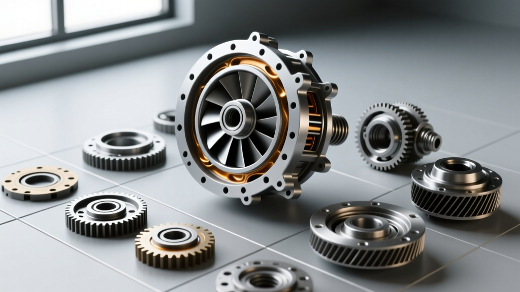
The most common beginner-friendly analogy compares a torque converter to two box fans facing each other. If you turn one fan on, the air it blows will spin the blades of the second fan, even though they aren't physically touching. In an automatic transmission, the 'air' is Automatic Transmission Fluid (ATF), and the 'fans' are the impeller (connected to the engine) and the turbine (connected to the transmission input shaft).
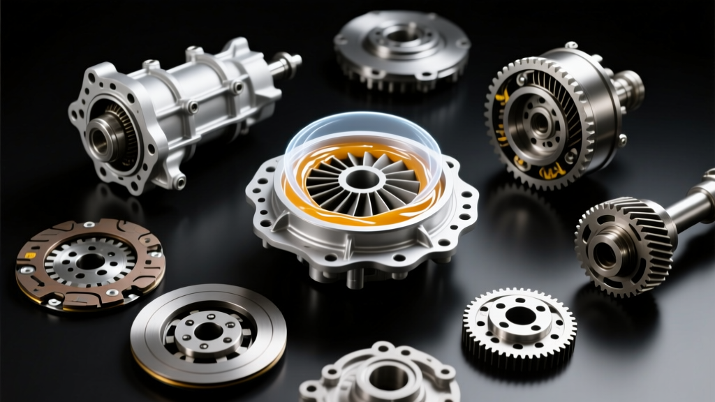
However, this analogy only scratches the surface. In reality, the impeller uses centrifugal force to violently accelerate modern, low-viscosity fluids like Dexron VI or Mercon LV outward against the turbine blades. This kinetic energy transfer creates immense heat and shear stress, which is why the internal clearances between the impeller and turbine are machined to tolerances as tight as 0.030 inches.
The Stator and Torque Multiplication
If a torque converter were just two fans, your car would feel incredibly sluggish off the line. This is where the stator comes in. Positioned between the impeller and the turbine, the stator is mounted on a one-way clutch (often called a sprag or roller clutch).
When you accelerate from a stop, the fluid returning from the turbine is moving in a direction that would actually oppose the engine's rotation. The stator's blades catch this returning fluid and redirect it back into the impeller in the direction of engine rotation. This 'recycling' of kinetic energy creates torque multiplication, effectively giving your engine a mechanical advantage of up to 2.5:1 at stall speed. Once the turbine speed catches up to roughly 90% of the impeller speed, the fluid flow direction changes, the stator's one-way clutch frees wheels, and the converter acts as a simple fluid coupling.
Torque Converter Clutch (TCC) and Lockup Mechanics
Fluid coupling is great for smooth acceleration, but it is inherently inefficient. The constant 'slip' between the impeller and turbine wastes fuel and generates excessive heat. To solve this, engineers introduced the Torque Converter Clutch (TCC).
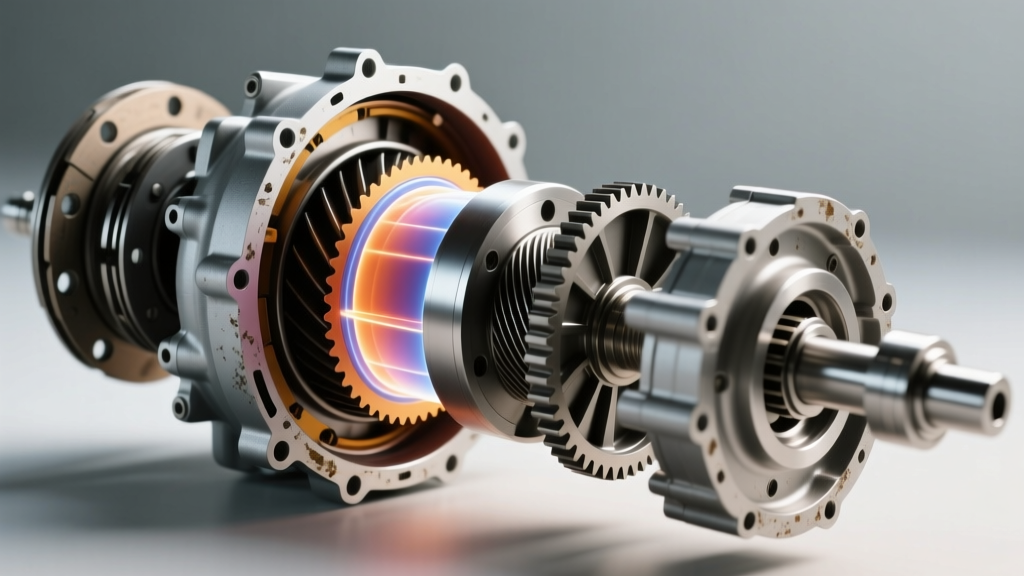
When you reach cruising speeds (usually between 35 and 50 mph, depending on the vehicle), the transmission's valve body directs pressurized ATF to apply a friction-lined clutch disc inside the converter. This physically locks the turbine to the impeller, creating a direct 1:1 mechanical connection. Modern transmissions use Pulse Width Modulation (PWM) solenoids—such as the AC Delco 214-1892 for GM applications or the Motorcraft SW-6167 for Ford—to 'slip' the TCC slightly during apply. This controlled micro-slip absorbs engine harmonics and prevents the drivetrain from shuddering.
Comparative Specs: Common Torque Converters in Modern Vehicles
To give you a better idea of how these systems vary across different platforms, here is a breakdown of common torque converter specifications. Keeping these specs in mind is vital if you are sourcing parts for a torque converter replacement.
| Transmission Model | Converter Diameter | Lockup Type | Total System Fluid Capacity | OEM Fluid Specification |
|---|---|---|---|---|
| GM 4L60E | 298mm (11.7 in) | Single Disc, On/Off | ~11.2 Quarts | ACDelco Dexron VI |
| GM 6L80 / 6L90 | 300mm (11.8 in) | Single Disc, PWM | ~12.5 Quarts | ACDelco Dexron VI |
| Ford 6R80 | 300mm (11.8 in) | Single Disc, PWM | ~13.1 Quarts | Motorcraft Mercon LV |
| ZF 8HP70 / 8HP75 | 215mm / 228mm | Twin-Damper, PWM | ~9.5 Liters | ZF Lifeguard 8 |
Diagnosing Failure: When Operation Turns into a Torque Converter Replacement
Understanding the mechanics makes diagnosing failures much easier. Here are the primary failure modes that lead to a torque converter replacement:
- TCC Shudder: This feels like driving over rumble strips at highway speeds. It occurs when the TCC friction material (often Raybestos GPZ or similar composite materials) degrades, or when the PWM solenoid fails to regulate apply pressure correctly. The clutch rapidly grabs and releases.
- Stator Sprag Failure: If the one-way clutch breaks and locks up, the stator cannot freewheel at higher speeds. This creates massive fluid restriction, leading to severe overheating and a drastic loss of top speed and fuel economy.
- Internal Debris and Contamination: If the transmission's internal clutches fail, metallic and friction debris circulates through the cooler lines and packs into the torque converter. Because a torque converter cannot be easily flushed or cleaned internally, a transmission overhaul always mandates a simultaneous torque converter replacement to prevent immediate re-contamination.
According to diagnostic guidelines from Sonnax Technical Resources, many perceived torque converter shudder issues are actually caused by degraded ATF losing its friction-modifying properties, or worn valve body bore issues failing to deliver adequate TCC apply pressure (which should typically be between 110 and 140 psi during lockup).
Real-World Costs and Installation Specs for 2026
If your diagnostic confirms that a torque converter replacement is unavoidable, you need to know what to expect regarding costs and installation standards. As of 2026, the average cost for a torque converter replacement ranges from $1,400 to $2,800 for most passenger vehicles, and up to $4,500 for heavy-duty diesel trucks (like those equipped with the Allison 1000 or Ford 10R140).
The part itself usually costs between $300 and $900, depending on whether you choose a stock OEM replacement or a high-performance billet-front-cover unit from manufacturers like Circle D or Vigilante. The bulk of the cost is labor, as the transmission must be completely removed from the vehicle to access the converter.
Critical Installation Specifications
A successful replacement relies on strict adherence to torque specs and measurements. If your mechanic skips these, your new converter will fail prematurely:
- Pilot Runout: The converter pilot hub must slide into the engine crankshaft flange smoothly. The runout (wobble) of the flexplate must be measured with a dial indicator and must not exceed 0.010 inches. Excessive runout will destroy the converter's internal front pump bushing within a few thousand miles.
- Flexplate-to-Converter Bolts: These bolts must be tightened to the manufacturer's exact specification (typically 35 to 45 lb-ft for most V8 applications) and secured with a medium-strength threadlocker (like Loctite 243) to prevent them from backing out and cracking the converter's front cover.
- Bellhousing Torque: When reinstalling the transmission, the bellhousing-to-engine block bolts must be torqued correctly. For example, on GM LS/LT engines, the M12 bolts require 37 lb-ft, while the M10 bolts require 26 lb-ft.
- Cooler Flushing: A mandatory 100% flush of the transmission cooler lines and radiator cooler is required. Any debris left in the cooling system will immediately migrate into the new torque converter.
For a deeper dive into the fluid dynamics and internal hydraulic circuits that govern these components, the tutorials at How a Car Works provide excellent visual breakdowns of the internal ATF flow paths. Armed with this knowledge, you can confidently discuss your repair options with your technician and ensure your vehicle's drivetrain is restored to factory specifications.