Introduction to Geely Drivetrain Electronics
Geely Automobile has rapidly evolved from a budget-friendly domestic automaker into a global powerhouse, largely due to its strategic acquisition of Volvo and the subsequent sharing of powertrain technologies. If you own a modern Geely vehicle—such as the Coolray, Azkarra (Boyue), or Okavango—your car likely utilizes the advanced 7DCT380 7-speed wet dual-clutch transmission or one of their newer Dedicated Hybrid Transmissions (DHT). At the heart of these complex gearboxes are highly sensitive electronic components. When your vehicle throws a check engine light or experiences harsh shifting, the culprit is often a failing speed sensor.
Testing a Geely transmission sensor might sound intimidating to a novice, but with a basic understanding of electrical circuits and a standard digital multimeter, you can accurately diagnose the issue before throwing expensive parts at the problem. This beginner-friendly explainer will walk you through the exact procedures, pinouts, and live data analysis required to verify the health of your transmission's input and output speed sensors.
Understanding the 7DCT380 Speed Sensors
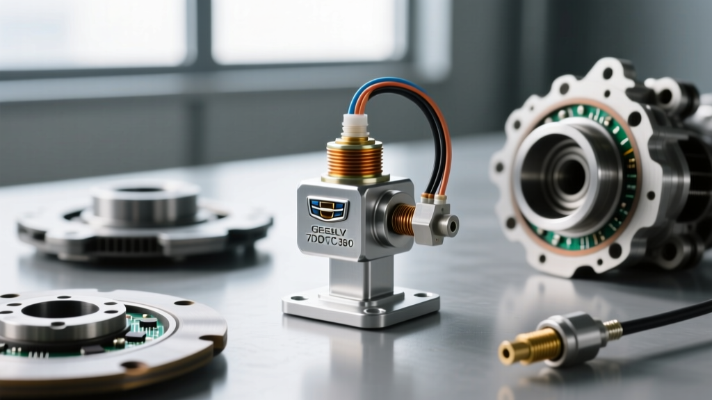
Unlike older automatic transmissions that used 2-wire Variable Reluctance (VR) sensors, modern Geely dual-clutch and hybrid transmissions rely on 3-wire Hall-effect speed sensors. These sensors are critical for the Transmission Control Module (TCM) to calculate clutch engagement points, monitor gear ratios, and detect internal slippage.
- Input Shaft Speed Sensor (ISS): Measures the rotational speed of the clutch drum directly connected to the engine.
- Output Shaft Speed Sensor (OSS): Measures the rotational speed of the final drive going to the wheels.
Because Hall-effect sensors require an external power source to operate, they output a clean, digital square-wave signal that the TCM can read even at extremely low speeds (like creeping in stop-and-go traffic). This is vital for the smooth low-speed maneuverability expected from a wet DCT.
Expert Insight: Never pierce the wiring harness with a test light or sharp probe to test a Hall-effect sensor. Piercing the wire insulation allows moisture to wick into the copper strands, causing green corrosion that will destroy the TCM driver circuit over time. Always use proper T-pin back-probes.
Tools Required for the Job
You do not need a dealership-level diagnostic rig to perform foundational sensor testing. Here is what you need to gather before starting:
| Tool | Purpose | Estimated Cost |
|---|---|---|
| Digital Multimeter (DMM) | Must measure DC Voltage, Resistance, and Frequency (Hz) | $35 - $150 |
| OBD2 Scanner with Live Data | Reads TCM PIDs (Parameter IDs) for RPM and slip | $40 - $200 |
| T-Pin Back-Probes | For safe electrical contact at the sensor connector | $5 - $10 |
| Automotive Oscilloscope (Optional) | Visualizes the square wave signal for advanced diagnostics | $150+ |
Phase 1: OBD2 Live Data Verification
Before crawling under the car or removing air intake ducts to access the transmission bell housing, let the car's computers tell you where the problem lies. Plug your OBD2 scanner into the DLC (Data Link Connector) under the dashboard and navigate to the Transmission Control Module live data stream.
What to Look For:
- ISS vs. OSS RPM: With the vehicle in Park or Neutral, the Input Shaft Speed should roughly match Engine RPM. When driving in a locked gear (e.g., 4th gear at cruising speed), the ISS and OSS should maintain a mathematically fixed ratio based on the gear's final drive. If the ISS reads 0 RPM while the engine is running, you have an open circuit or a dead sensor.
- Slippage PIDs: If the TCM detects a variance between expected and actual speed, it will log a slip fault. Geely's TCM is highly sensitive; a variance of just 50 RPM for more than 2 seconds can trigger limp mode.
- Temperature Correlation: Speed sensors rarely fail in isolation. Check the Transmission Fluid Temperature (TFT) PID. If the TFT reads -40°F or 300°F, you likely have a shared 5V reference circuit failure that is also taking down your speed sensors.
Phase 2: Physical and Electrical Pinpoint Tests
If live data confirms a missing or erratic speed signal, it is time to test the physical Geely transmission sensor. Locate the sensor on the transmission casing. On the 7DCT380, the sensors are typically inserted radially into the bell housing and clutch drum areas, secured by a single M6 flange bolt.
Step 1: The 5-Volt Reference Test
Disconnect the sensor harness connector. Turn the ignition to the 'ON' position (engine off). Set your multimeter to DC Volts. Place the black probe on a known good chassis ground and use a back-probe on the red wire to test the harness side of the connector.
- Expected Result: You should read exactly 4.9V to 5.1V. This is the reference voltage supplied by the TCM.
- If 0V: You have a broken wire between the TCM and the sensor, or a blown TCM internal fuse.
- If 12V: You are probing the wrong wire, or the vehicle uses an older 12V pull-up circuit (rare on post-2018 Geely models).
Step 2: Ground Circuit Integrity
Keep the multimeter in DC Volts. Move the red probe to the battery positive terminal, and use the black probe to test the black/ground wire on the harness connector.
- Expected Result: You should read full battery voltage (approx. 12.4V). This confirms the ground path back to the TCM is complete.
Step 3: Signal Wire and Waveform Test
Reconnect the sensor harness. Back-probe the center signal wire (usually green or yellow). Set your multimeter to measure Frequency (Hz) or Duty Cycle (%). Start the engine and raise the drive wheels safely on jack stands, or have an assistant rev the engine in gear if doing a stall test (exercise extreme caution).
- Expected Result: At idle in gear, you should see a fluctuating Hz reading that increases linearly with wheel speed. If your meter supports it, a 50% duty cycle square wave is the hallmark of a healthy Hall-effect sensor.
Interpreting Multimeter Readings
Use this quick-reference chart to diagnose your findings:
| Test Point | Multimeter Setting | Healthy Reading | Fault Indication |
|---|---|---|---|
| Supply Wire (Harness) | DC Volts | 5.0V | Open circuit, TCM fault |
| Ground Wire (Harness) | DC Volts (Reverse) | 12.4V (Battery V) | Corroded TCM ground pin |
| Signal Wire (Connected) | Frequency (Hz) | Varies with RPM | Dead sensor, damaged reluctor ring |
| Signal Wire (Connected) | DC Volts | 2.5V (Average) | Short to ground if 0V; Short to power if 5V+ |
Common Geely OBD2 Codes Related to Speed Sensors
When a sensor fails the electrical tests above, the TCM will store specific Diagnostic Trouble Codes (DTCs). According to standard OBD-II fault code databases, the most common Geely-specific codes include:
- P0715: Input/Turbine Shaft Speed Sensor Circuit Malfunction. (Usually points to a wiring break or internal sensor coil failure).
- P0717: Input Shaft Speed Sensor Circuit No Signal. (Often caused by metallic debris on the sensor's magnetic tip blinding it to the reluctor wheel).
- P0720: Output Speed Sensor Circuit Malfunction.
- P0722: Output Speed Sensor Circuit No Signal.
For deeper electrical schematics and general transmission sensor theory, resources like AA1Car's transmission sensor library offer excellent baseline diagrams that apply to Geely's Bosch and Continental TCM architectures.
Replacement Specs and Torque Values
If your testing confirms a dead sensor, replacement is straightforward but requires strict adherence to torque specifications. The 7DCT380 casing is made of lightweight cast aluminum, which strips easily if over-torqued.
- OEM Part Cost: Genuine Geely/Volvo Hall-effect speed sensors typically retail between $45 and $75 depending on the dealer. Avoid $15 eBay knock-offs, as their internal potting compound often fails under high transmission fluid temperatures (up to 130°C / 266°F).
- Mounting Bolt: M6 x 16mm flange bolt.
- Torque Spec: 9 Nm (80 in-lbs). Do not exceed 10 Nm.
- O-Ring Seal: Always lubricate the new sensor's rubber O-ring with fresh synthetic DCT fluid before insertion to prevent rolling or tearing, which will cause a slow external fluid leak.
Summary
Diagnosing a Geely transmission sensor does not require a master technician's certificate, just a methodical approach. By starting with OBD2 live data, verifying the 5V reference and ground circuits, and measuring the signal output, you can confidently isolate the fault. Whether you are dealing with a simple chafed wire near the bell housing or a failed internal Hall-effect chip, these testing procedures will save you from unnecessary transmission teardowns and expensive dealership diagnostic fees.