The Physics of Torque Converter Stall Speed Explained
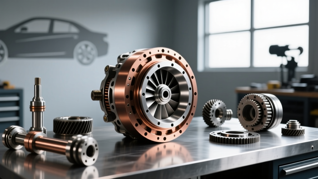
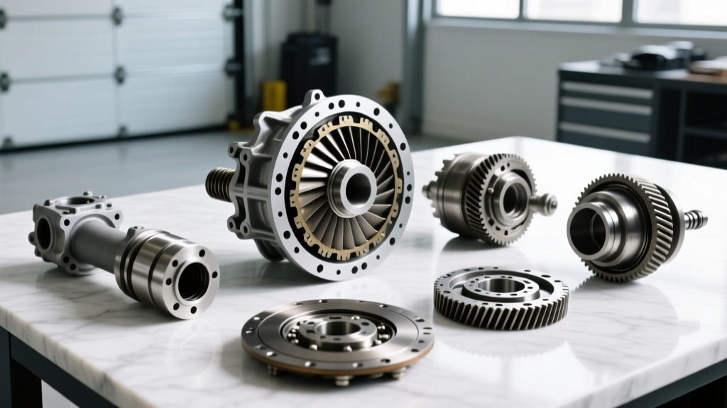
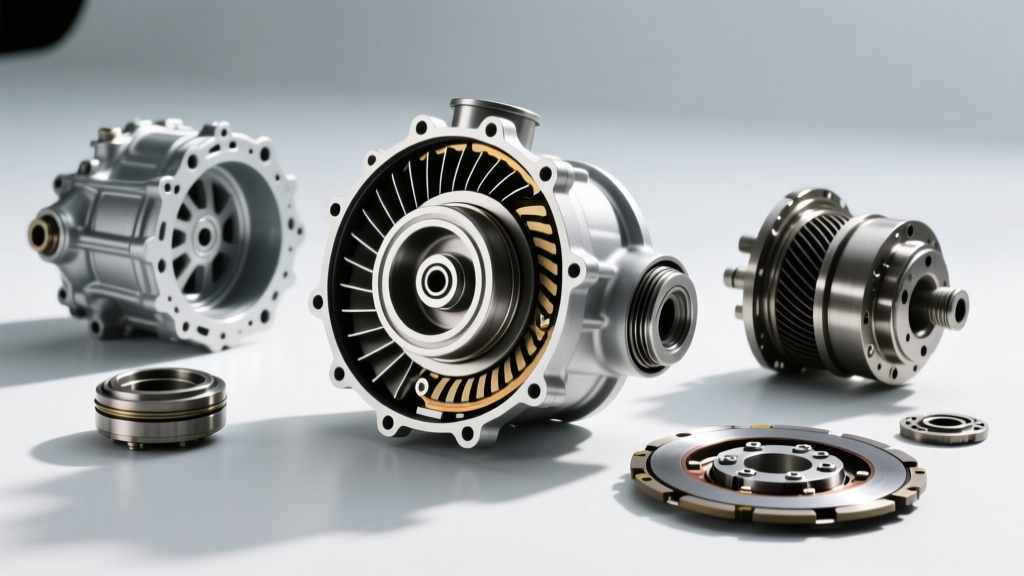
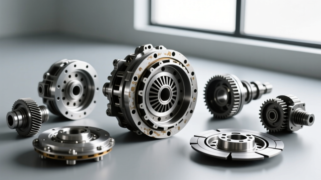
To properly diagnose automatic transmission issues, technicians and enthusiasts must understand the hydrodynamic principles governing the torque converter. At its core, a torque converter is a fluid coupling device that multiplies engine torque using three primary internal components: the impeller (pump), the turbine, and the stator. The impeller is driven directly by the engine via the flexplate, pushing transmission fluid outward and into the turbine, which is splined to the transmission input shaft.
Stall speed is defined as the maximum engine RPM achievable when the transmission is in a forward gear, the output shaft is held completely stationary (via the brakes or a mechanical load), and the throttle is held at Wide Open Throttle (WOT). It is crucial to understand that a torque converter does not have a single, fixed 'stall speed.' Instead, stall speed is entirely dependent on the engine's torque output. An engine producing 450 lb-ft of torque will push the same torque converter to a higher stall RPM than a stock engine producing 250 lb-ft of torque. Understanding this relationship is the first step before considering the removal of torque converter units for replacement or upgrading.
Furthermore, the stator's one-way clutch plays a vital role. During the stall phase, the stator remains locked, redirecting fluid returning from the turbine back into the impeller in the direction of rotation. This fluid redirection is what creates torque multiplication (often between 2.0:1 and 2.5:1). If the stator clutch fails and freewheels in both directions, torque multiplication is lost, resulting in severe sluggishness off the line and drastically altered stall test results.
Step 1: Preparation and Safety Protocols
Performing a stall test generates immense heat and places significant stress on the drivetrain. In 2026, with modern transmission fluids like Dexron ULV and Mercon LV operating in tighter thermal windows, preparation is non-negotiable. Follow these steps to prepare the vehicle:
- Verify Fluid Level and Condition: Check the ATF level with the engine running and the transmission at operating temperature. Inspect the fluid for a burnt smell or metallic particulates, which indicate existing internal damage.
- Monitor Transmission Temperature: Connect a high-quality bi-directional scan tool or an inline digital thermometer (such as the Snap-on MT2800A). The ATF temperature MUST be between 160°F and 200°F (71°C - 93°C) before testing. Cold fluid will yield falsely high stall RPMs due to increased viscosity and drag.
- Install a Line Pressure Gauge: Hook up a 0-300 PSI mechanical or digital gauge to the transmission's main line pressure port. Monitoring line pressure during the test ensures the pump is functioning and the clutches are being applied with adequate hydraulic force.
- Secure the Vehicle: Use heavy-duty wheel chocks on all four wheels. Ensure the parking brake is fully engaged and the service brake pedal is firm. A spongy brake pedal can lead to the vehicle launching through the stall test, causing catastrophic damage or injury.
Step 2: Executing the Stall Test
Once the vehicle is secured and temperatures are verified, you can execute the test. This process must be precise and brief to prevent fluid degradation and component failure.
- Engage the Gear: Shift the transmission into Drive (D) or Low (1), depending on the manufacturer's service manual specifications. For most planetary gearsets, testing in D1 or manual low provides the most accurate load on the holding clutches.
- Apply Brakes Firmly: Press the service brake pedal to the floor with your left foot. Do not pump the brakes; maintain steady, maximum hydraulic pressure.
- Apply Wide Open Throttle (WOT): Quickly but smoothly push the accelerator pedal to the floor with your right foot.
- Record the RPM and Pressure: Watch the tachometer and the line pressure gauge. Note the exact RPM where the engine stops climbing and 'stalls' against the converter. NEVER hold WOT for more than 5 seconds.
- Cool Down: Immediately release the throttle, shift into Neutral or Park, and allow the transmission to idle and cool for at least two minutes before repeating the test in Reverse or re-testing in Drive.
Expert Warning: Never perform a stall test on a transmission that is already exhibiting severe slipping, low line pressure, or massive fluid leaks. The extreme heat generated in 5 seconds can weld clutch plates together or melt synthetic ATF, turning a minor diagnostic issue into a total unit failure.
Step 3: Analyzing the Data
Comparing your recorded stall RPM against factory specifications will isolate the fault to either the engine, the transmission's internal holding components, or the torque converter itself. Below is a diagnostic matrix for common transmission platforms:
| Transmission Model | Stock Stall RPM Range | Low Stall Indication (-300 RPM) | High Stall Indication (+300 RPM) |
|---|---|---|---|
| GM 4L60E / 4L65E | 1800 - 2100 | Engine breathing issue, restricted exhaust, or incorrect low-stall TC installed. | Slipping 3-4 clutch pack, broken 2-4 band, or failed stator one-way clutch. |
| Ford 6R80 | 2000 - 2400 | Severe engine torque deficit, ECU limp mode, or wrong flexplate depth. | Internal seal leak (e.g., molded leadframe drum seals) or failing TCC. |
| ZF 8HP (8HP70/75) | 2200 - 2500 | Aggressive ECU torque management limiting throttle, or wrong mechatronic adaptation. | Worn 'A' or 'B' clutch packs, or a sheared turbine hub spline. |
For a deeper dive into internal component failures, refer to the diagnostic flowcharts provided by Sonnax Torque Converter Basics, which detail how stator pitch and fin angles dictate these RPM thresholds.
Modern ECU Torque Management Interference
When diagnosing late-model vehicles (2018-2026), technicians frequently encounter artificially low stall speeds. Modern Engine Control Units (ECUs) and Transmission Control Modules (TCMs) communicate via high-speed CAN-FD networks. When the ECU detects that the brake pedal is depressed while the throttle is at WOT, it recognizes a 'brake-torque' event. To protect the drivetrain axles and differentials, the ECU will aggressively pull ignition timing, cut fuel injector pulse width, or electronically close the throttle body (Drive-By-Wire) to limit engine torque output.
If your stall test yields an RPM 500-800 below the factory specification, but the engine feels completely healthy during normal driving, you are likely fighting ECU torque management. In these cases, utilizing a specialized tuning suite to temporarily disable 'Brake Torque Limitation' or performing a 'Flash Stall' test (briefly flashing the throttle to WOT without holding it) is required to get accurate hydrodynamic data.
When Results Dictate the Removal of Torque Converter
Diagnostic data must drive your repair strategy. If your stall test results fall outside the acceptable parameters after accounting for engine health and ECU intervention, physical inspection is mandatory. Specifically, the removal of torque converter assemblies becomes necessary under the following conditions:
- Stator Clutch Failure: If stall RPM is significantly higher than spec, accompanied by a severe lack of low-end torque multiplication and poor fuel economy at highway speeds (due to excessive slippage), the internal stator one-way clutch has likely failed. The converter must be removed, cut open, and rebuilt or replaced.
- Turbine Hub Spline Wear: A high-pitch whining noise during the stall test, combined with metallic debris on the transmission magnet, often points to the turbine hub stripping against the transmission input shaft. This requires dropping the transmission.
- TCC Contamination: If the Torque Converter Clutch (TCC) is shuddering and stall speeds are erratic, friction material from the TCC may be contaminating the transmission's valve body and solenoid pack. Flushing is rarely sufficient; the removal of torque converter components is required to eliminate the source of the debris.
For more advanced diagnostic scenarios involving stator failures and internal fluid dynamics, the technical bulletins at Transmission Digest offer excellent case studies on modern ZF and GM 10-speed units.
Quick Overview: The Removal Process and Torque Specs
Once you have confirmed the need for replacement, executing the removal of torque converter hardware requires strict adherence to factory torque specifications to prevent catastrophic drivetrain failure upon reassembly. The general procedure involves:
- Fluid Evacuation and Driveshaft Removal: Drain the transmission pan. Remove the rear driveshaft and mark the pinion yoke for balance preservation.
- Flexplate to TC Bolt Removal: Rotate the crankshaft via the harmonic balancer bolt (never by the flexplate itself, as this can warp the thin metal and cause runout issues) to access the torque converter-to-flexplate bolts through the inspection cover.
- Transmission Crossmember and Linkage: Support the transmission with a specialized jack. Remove the crossmember, shift linkage, electrical connectors, and cooler lines.
- Bellhousing Separation: Unbolt the transmission from the engine block. Carefully slide the transmission straight back. Critical Step: Ensure the torque converter remains fully seated against the flexplate and does not drop forward. If the converter pulls away from the transmission pump gear, it will tear the front pump seal and crack the pump housing upon reinstallation.
Reinstallation Torque Specifications:
- GM 4L60E / 6L80: Torque converter to flexplate bolts must be tightened to 46 lb-ft. Always apply a medium-strength threadlocker (e.g., Loctite 243) to prevent these bolts from backing out, which can result in the converter tearing through the flexplate.
- Ford 6R80 / 10R80: Flexplate to crankshaft bolts are typically torqued to 59 lb-ft plus an additional 90-degree turn. Torque converter to flexplate nuts are torqued to 36 lb-ft.
- ZF 8HP Series: Ensure the flexplate runout is measured with a dial indicator before installing the new converter. Runout exceeding 0.020 inches (0.5mm) will cause premature wear to the converter hub and transmission front pump bushing.
In 2026, the average cost for professional removal and replacement (R&R) of a torque converter, including a high-quality remanufactured unit (from brands like Yank, Precision Industries, or Sonnax) and fresh synthetic ATF, ranges from $1,400 to $2,800 depending on the vehicle's drivetrain configuration (2WD vs. 4WD) and local labor rates. By performing a rigorous, data-driven stall test first, you ensure that this significant investment directly addresses the root cause of your drivetrain's performance issues.