The Hidden Bottleneck: Why Cooler Size and Line Diameter Must Match
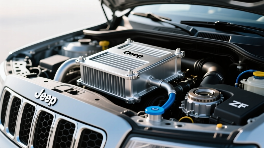
As we navigate the 2026 landscape of heavy-duty towing and high-performance off-roading, modern transmissions like the GM 10L80 and ZF 8HP are engineering marvels. However, they are also notorious heat generators. While many enthusiasts immediately focus on transmission cooler size selection, they often overlook a critical restriction point: the plumbing. Installing a massive 30,000 GVWR stacked-plate cooler is entirely pointless if you choke the system with undersized, degrading, or improperly rated rubber transmission cooler lines. The fluid dynamics of your cooling circuit rely on a delicate balance of core volume, fin density, and unrestricted hose diameter. This step-by-step guide will walk you through calculating your thermal load, selecting the right core, and properly integrating high-flow rubber lines to ensure your drivetrain survives the harshest conditions.
Step 1: Calculate Your GVWR and Transmission Heat Load
Transmission cooler sizing is not a guessing game; it is dictated by your vehicle's Gross Vehicle Weight Rating (GVWR) and your specific use case. The GVWR rating on a cooler indicates the maximum vehicle weight it can effectively cool under standard towing conditions.
Matching GVWR to Your Rig
- Light Duty / Commuter (Up to 10,000 lbs GVWR): Standard passenger vehicles or light SUVs with a 4L60E or 6R80. A basic tube-and-fin cooler is usually sufficient.
- Medium Duty / Half-Ton Towing (10,000 - 18,000 lbs GVWR): Half-ton trucks (e.g., F-150, Silverado 1500) towing campers or boats. You need a plate-and-fin or entry-level stacked-plate design.
- Heavy Duty / Commercial (18,000 - 30,000+ lbs GVWR): 3/4-ton and 1-ton trucks with Allison 1000 or GM 6L80/10L80 transmissions towing fifth wheels or heavy equipment. A high-flow stacked-plate cooler is mandatory.
Expert Insight: If you have modified your vehicle with larger aftermarket tires, a lift kit, or a heavy steel bumper, you must bump up your cooler GVWR rating by at least one tier to compensate for the increased parasitic drivetrain loss and heat generation.
Step 2: Choose the Right Cooler Core Design and Dimensions
Once your GVWR requirement is established, you must select the physical dimensions and core architecture that will fit behind your grille or in your auxiliary mounting location. Below is a breakdown of the three primary cooler architectures available on the market today.
| Cooler Architecture | Flow Efficiency | Thermal Transfer Rate | Best Application | Example Model (2026) |
|---|---|---|---|---|
| Tube-and-Fin | Low (Restrictive) | Moderate | Light duty, older 4-speed autos | Hayden 676 Rapid-Cool |
| Plate-and-Fin | Medium | High | Half-ton towing, daily drivers | Hayden 678 Rapid-Cool |
| Stacked-Plate | Very High (Low Drop) | Maximum | Heavy towing, racing, 8-10 speeds | Derale 15850 Hyper-Cool |
For modern 8-speed and 10-speed transmissions, the high flow rates demanded by the internal bypass valves require the low-pressure-drop environment of a stacked-plate cooler. Restricting flow on a ZF 8HP can trigger limp mode or cause the internal thermostat to malfunction.
Step 3: Selecting and Sizing Rubber Transmission Cooler Lines
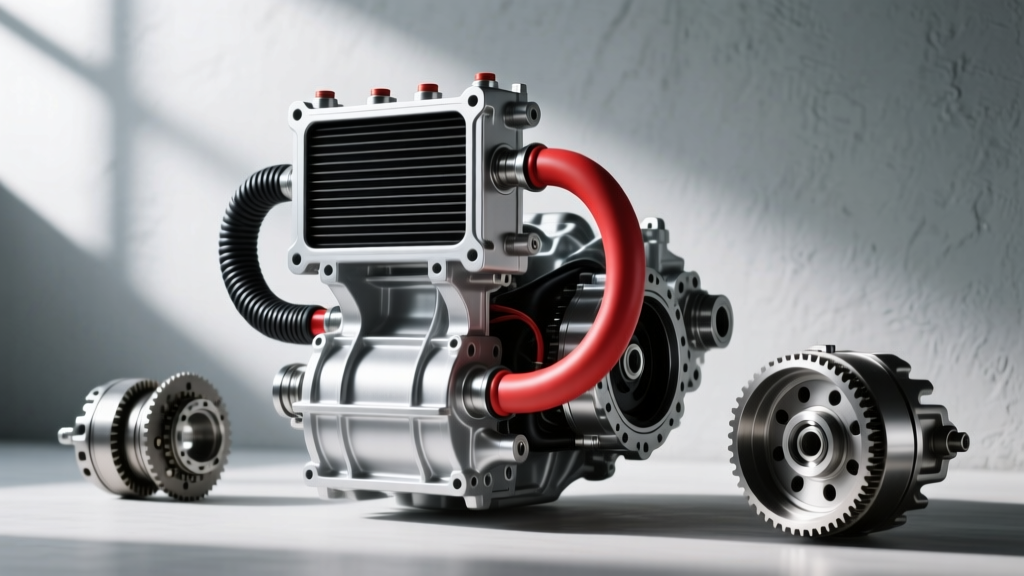
This is where many DIY installations fail. The rubber transmission cooler lines act as the arteries of your cooling system. If they collapse under suction, swell under pressure, or degrade from heat, your expensive cooler becomes useless.
The SAE J1532 Standard
Never use standard fuel hose or generic hydraulic hose for transmission cooling. Transmission fluid (especially modern synthetic blends like Dexron ULV or Mercon LV) operates at high temperatures (up to 250°F in the return line before the cooler) and contains aggressive detergents that will cause standard rubber to swell, soften, and eventually burst. You must purchase hose that explicitly meets the SAE J1532 specification for transmission oil cooler applications. According to the Gates Corporation, their FleetRunner and specific transmission oil cooler hoses feature an inner tube designed specifically to resist ATF swelling and ozone degradation.
Diameter Sizing
Most factory transmission hard lines are 3/8-inch OD. When transitioning to rubber transmission cooler lines, you must maintain or increase the Inner Diameter (ID) to prevent flow restriction.
- 3/8" ID Hose: Standard for most passenger cars and light trucks. Matches standard 3/8" barb fittings on coolers like the Hayden 678.
- 1/2" ID Hose: Required for heavy-duty applications, Allison transmissions, and high-flow stacked-plate coolers like the Derale Hyper-Cool series. Stepping up to 1/2" ID reduces fluid velocity, increasing dwell time inside the cooler plates for superior heat extraction.
Step 4: Routing, Cutting, and Securing the Lines
Proper routing ensures longevity and prevents catastrophic fluid loss. Follow these mechanical best practices when installing your rubber lines.
Clearance and Looming
Transmission fluid fires are a real hazard if a line bursts near the exhaust. Maintain a minimum of 4 inches of clearance between your rubber lines and any exhaust components. If you must cross near an exhaust pipe, wrap the rubber transmission cooler lines in a high-temperature silicone or fiberglass fire sleeve (rated for 500°F+). Additionally, slide a split nylon wire loom over the hoses anywhere they pass through the radiator support or frame rails to prevent chafing from chassis vibration.
Clamp Selection and Torque Specs
Do not use standard worm-gear clamps. The band slots on worm-gear clamps act like a cheese grater on soft rubber ATF hose as it expands and contracts under thermal cycling. Instead, use Constant-Tension T-Bolt Clamps or Fuel Injection Style Spring Clamps.
Pro-Tip on AN Fittings: If you are adapting your rubber lines to -6 AN or -8 AN aluminum barbed fittings on a custom stacked-plate cooler, lubricate the barb with a drop of clean ATF before sliding the hose on. Tighten the aluminum AN adapter to the cooler manifold to exactly 18-20 ft-lbs using an aluminum-specific torque wrench to avoid stripping the threads on the cooler plate.
Step 5: Flow Testing and Final System Verification
Before taking the vehicle on the highway, you must verify that the rubber transmission cooler lines are flowing correctly and that the system is free of air pockets.
- Top Off the Fluid: Modern transmissions like the GM 6L80 hold roughly 11.2 quarts total, but adding an external cooler and 10 feet of 1/2" rubber lines will add nearly 1.5 quarts to the system capacity. Fill to the cold mark on the dipstick or follow the OEM temperature-based fill procedure via the scan tool.
- The Idle Cycle Test: Start the engine, cycle the shifter through all gears (pausing for 3 seconds in each), and return to Park. Let the engine idle for 15 minutes. Inspect every hose barb and clamp for weeping.
- Thermal Verification: Using an infrared thermometer, check the temperature of the hard line exiting the transmission (should be 160°F - 190°F at operating temp). Then, check the rubber return line coming back from the cooler. You should see a temperature drop of at least 30°F to 50°F, proving the cooler core and the unrestricted rubber lines are functioning as a unified system.
By meticulously matching your transmission cooler size selection with high-quality, correctly sized plumbing, you eliminate the thermal bottlenecks that destroy drivetrains. For further reading on fluid dynamics and hose specifications, consult the engineering resources at Hayden Automotive and Derale Performance. Protect your investment by treating your cooling lines with the same respect as the cooler itself.