The Critical Role of the Fan Clutch in Class 8 Thermal Management
When discussing clutch system diagnostics in heavy-duty commercial vehicles, most technicians immediately think of the drivetrain. However, the semi truck fan clutch is a mission-critical friction and engagement device that directly dictates engine thermal efficiency, horsepower retention, and overall drivetrain survivability. A failing fan clutch doesn't just cause overheating; it induces severe parasitic drag, triggers engine ECU derates, and can mimic transmission slipping symptoms due to sudden load variations on the front-end accessory drive (FEAD).
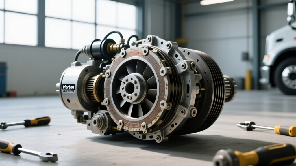
In the modern 2026 landscape of Class 8 trucks, fan clutches have evolved from simple viscous fluid couplings into highly sophisticated pneumatic and electromagnetic actuation systems. Diagnosing these units requires a rigorous understanding of friction materials, air gap tolerances, and solenoid circuitry. This technical deep-dive provides a definitive inspection checklist for heavy-duty fan clutches, focusing on industry-standard architectures like the Horton DriveMaster and Kysor electromagnetic systems.
Core Engagement Mechanisms: Pneumatic vs. Electromagnetic
Before executing an inspection, it is vital to identify the actuation architecture. The diagnostic approach varies wildly depending on whether the clutch relies on compressed air or magnetic flux to manage the friction interface.
Pneumatic Architecture (Spring-Engaged, Air-Disengaged)
The vast majority of Class 8 pneumatic fan clutches operate on a failsafe "spring-engaged, air-disengaged" principle. When the engine is cold, or if the truck loses air pressure, a heavy-duty internal spring forces the friction liner against the drive plate, locking the fan to the water pump pulley. To disengage the fan (reducing parasitic drag and saving up to 40 HP), the truck's air system routes 90-120 PSI through a solenoid valve into the clutch air chamber, compressing the spring and separating the friction surfaces.
Electromagnetic Architecture (Electro-Actuated)
Electromagnetic clutches utilize a 12V DC coil to generate a magnetic field that pulls an armature against a rotor. The friction interface is engaged electrically. These systems rely on precise air gaps (typically measured in thousandths of an inch) and are highly susceptible to voltage drops, coil burnout, and friction surface glazing.
Expert Diagnostic Note: Thermal hysteresis is a common misdiagnosis. If a pneumatic clutch cycles rapidly (chatter) at the engagement threshold, do not immediately replace the clutch. First, verify the calibration of the engine coolant temperature (ECT) sensor and the integrity of the bimetallic switch or ECU PWM signal controlling the air delivery valve.
The Definitive Semi Truck Fan Clutch Inspection Checklist
Perform this checklist with the engine OFF, batteries disconnected (for electromagnetic testing), and the air system fully bled down to zero PSI to ensure the pneumatic clutch is in its natural, spring-engaged failsafe state.
Phase 1: Visual and Physical Routing Inspection
- Air Line Integrity (Pneumatic): Inspect the 3/8-inch OD polyurethane air supply line. Look for chafing against the engine block, thermal degradation near the exhaust manifold, and brittle fittings. A micro-leak here will cause the clutch to slip under high fan load, generating immense heat and destroying the friction liner.
- Electrical Harness & Connectors: Check the Weather-Pack connectors leading to the air solenoid valve or the electromagnetic coil. Look for green copper oxidation (verdigris) which increases circuit resistance. A voltage drop of just 1.5V across a corroded connector can prevent an electromagnetic coil from generating sufficient magnetic flux to fully seat the armature.
- Bracket and Pulley Alignment: Use a straight edge across the water pump pulley and the fan clutch hub. Misalignment exceeding 0.030 inches will cause uneven friction liner wear and severe front-bearing degradation.
Phase 2: Friction Disk and Bearing Measurement
Friction material degradation is the primary cause of fan clutch slip and chatter. You must measure the liner thickness and check the hub bearings for axial and radial play.
| Component Specification | Horton DriveMaster (Pneumatic) | Kysor / EM Series (Electromagnetic) |
|---|---|---|
| Friction Liner Min. Thickness | 0.125 inches (3.17 mm) | 0.090 inches (2.28 mm) |
| Air Gap Tolerance | N/A (Spring tension dependent) | 0.015" - 0.030" (Shim adjustable) |
| Actuation Force / Pressure | 90 - 120 PSI (Air Chamber) | 12V - 14V DC (Magnetic Coil) |
| Hub Mounting Bolt Torque | 35 - 45 lb-ft (Grade 8, 3/8"-16) | 40 - 50 lb-ft (Grade 8, 3/8"-16) |
| Solenoid Coil Resistance | 8 - 12 Ohms (Air Valve Solenoid) | 10 - 15 Ohms (Internal EM Coil) |
Source data adapted from Horton Fan Drives & Clutches Technical Documentation and heavy-duty OEM service manuals.
Diagnostic Flowchart: Slipping, Chatter, and Non-Engagement
When a driver reports thermal issues or unusual front-end noise, map the symptom to the underlying mechanical failure using this framework:
Symptom 1: Clutch Slipping (Engine Overheating under Load)
- Pneumatic Root Cause: Insufficient air pressure reaching the chamber (check for kinked lines or failing air delivery valve), or the friction liner is contaminated with oil/coolant, drastically reducing the coefficient of friction.
- Electromagnetic Root Cause: Excessive air gap due to worn friction material, preventing the magnetic field from fully pulling the armature. The clutch "slips" magnetically and mechanically, generating extreme heat that can warp the rotor.
Symptom 2: Clutch Chatter (Rhythmic Grinding or Squealing)
- Root Cause: Glazed friction liners. If the clutch is forced to slip repeatedly (often due to a faulty ECU temperature threshold map), the organic or sintered iron friction material overheats and forms a hard, glassy surface. When the clutch attempts to engage, it bounces off the glazed surface, creating a high-frequency chatter that vibrates through the FEAD belt and water pump bearings.
- Corrective Action: The friction disc must be replaced. Attempting to sand or resurface a heavy-duty fan clutch liner is a temporary band-aid that will fail within 5,000 miles under high-load mountain driving conditions.
Symptom 3: Fails to Disengage (Constant High RPM Fan Roar)
- Pneumatic Root Cause: This is the designed failsafe. If the truck loses air pressure, the clutch locks ON to save the engine. However, if air pressure is verified at 120 PSI and the clutch remains locked, the internal return spring may be fatigued, or the internal O-rings in the air chamber have swollen and bound the actuator piston.
- Electromagnetic Root Cause: A short to ground in the wiring harness is providing constant 12V power to the coil, or the coil has suffered an internal thermal short, retaining residual magnetism even when power is cut.
Advanced Multimeter and Pressure Testing
Move beyond visual inspections by utilizing precision diagnostic tools to verify the actuation circuits.
Solenoid and Coil Resistance Testing (Ohms)
Disconnect the electrical connector at the fan clutch or the frame-mounted air solenoid. Set your digital multimeter (DMM) to the Ohms (Ω) setting. Probe the terminals. A reading of OL (Open Line) indicates a broken internal coil winding—the component is dead and must be replaced. A reading below 4 Ohms indicates an internal short circuit, which will blow the ECU fuse or fry the PWM driver board. Refer to Fleet Owner's heavy-duty component troubleshooting guides for specific OEM wiring schematics.
Pneumatic Supply Validation (PSI)
Install a mechanical 0-160 PSI inline gauge between the air delivery valve and the fan clutch air line. Command the fan OFF via the engine ECM (or wait for the engine to reach operating temperature of 195°F+). The gauge must read a minimum of 90 PSI. If the pressure drops to 60 PSI during engagement, the air chamber diaphragm is leaking internally, or the supply line is restricted.
Replacement Intervals and Sourcing OEM Components
Heavy-duty fan clutches are not lifetime components. Under severe-duty cycles (logging, heavy haul, frequent PTO usage), expect to inspect and potentially replace the friction liner and hub bearings every 350,000 to 450,000 miles.
When sourcing replacements, avoid cheap aftermarket knock-offs that utilize inferior friction compounds. A genuine OEM or premium Tier-1 remanufactured fan clutch assembly (such as those from Horton or Kysor) typically ranges from $650 to $950. While the upfront cost is higher, the precise friction modulation prevents catastrophic water pump bearing failure and avoids the massive fuel penalty associated with a continuously locked cooling fan. Always replace the hub mounting hardware with new Grade 8 flanged bolts, torquing them to 35-45 lb-ft using a calibrated torque wrench, and apply a medium-strength threadlocker (e.g., Loctite 243) to prevent vibrational loosening.
Conclusion
The semi truck fan clutch is a vital friction-based engagement system that demands the same diagnostic respect as a transmission clutch. By adhering to this technical inspection checklist—verifying air gaps, measuring friction material thickness, and rigorously testing pneumatic and electrical actuation circuits—technicians can accurately diagnose slip, chatter, and engagement failures. Mastering these diagnostics ensures optimal engine thermals, protects the front-end accessory drive, and keeps Class 8 fleets running efficiently on the road.