Why Your Factory Cooling System Needs Help
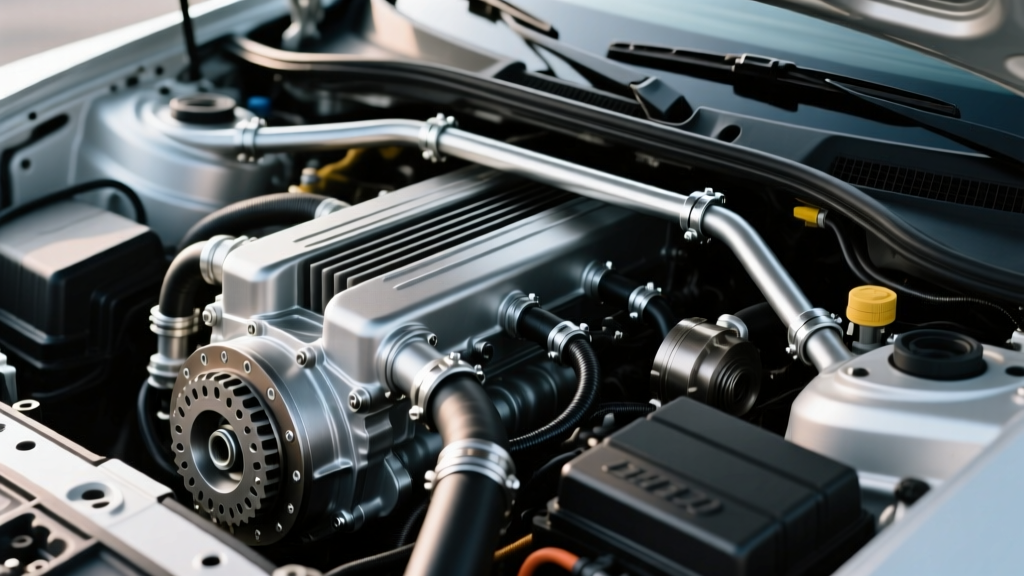
If you are towing a 7,000-pound travel trailer or pushing through stop-and-go traffic in the summer heat, your factory transmission cooling system is likely operating on the edge of its thermal limits. As of 2026, OEMs are designing vehicles with aggressive aerodynamics and tighter grille openings for EPA compliance, which inherently restricts ambient airflow to the heat exchangers. Transmissions like the GM 6L80, Ford 10R80, and the ubiquitous ZF 8HP generate immense friction heat, especially when the torque converter is unlocked during heavy hauling.
Installing an auxiliary cooler is one of the most cost-effective modifications you can make to extend the life of your drivetrain. However, the most critical part of the job isn't just bolting the cooler to the bumper; it is correctly routing the transmission cooler lines to ensure optimal fluid dynamics and prevent catastrophic pressure drops. This beginner-friendly explainer will walk you through the exact science and mechanical steps required to do it right the first time.
The Golden Rule: Pressure vs. Return Lines
The biggest mistake beginners make is tapping into the wrong line, effectively reversing the intended flow of the factory thermal management system. To understand how to route your new lines, you must understand the factory loop.
- Pressure Line (Out): Hot fluid leaves the transmission under high pressure.
- Radiator Loop: Fluid enters the bottom tank of the engine radiator, where it sheds the bulk of its heat to the engine coolant.
- Return Line (In): Fluid exits the radiator and returns to the transmission.
Where does the auxiliary cooler go? You must splice the auxiliary cooler into the return line. This means the fluid travels from the Transmission → Radiator → Auxiliary Cooler → Back to the Transmission. By placing the auxiliary cooler after the radiator, you ensure the fluid receives the deepest, final stage of cooling right before it re-enters the transmission pan and lubricates the valve body and clutch packs.
How to Identify the Return Line
Do not guess which line is which based on their physical position (top vs. bottom), as this varies wildly between a Chevy Silverado and a Ford F-150. Use the "Cold Start Test":
- Start the engine cold (after sitting overnight).
- With your foot firmly on the brake, shift the transmission into Drive for 10 seconds, then Reverse for 10 seconds.
- Turn off the engine and carefully feel the two metal transmission cooler lines near the radiator.
- The line that is noticeably warmer is the Pressure (Out) line. The cooler line is the Return (In) line. You will cut the Return line for your installation.
Tools, Parts, and Specifications
Using the correct materials is non-negotiable. Standard fuel hose will degrade and swell when exposed to the harsh detergents in modern synthetic ATF (Automatic Transmission Fluid). Below is the specification table you need for a standard 3/8-inch system found on most half-ton and three-quarter-ton trucks.
| Component | Specification / Part Type | Application Notes |
|---|---|---|
| Hose | 3/8" ID SAE J1019 ATF Hose | Must be rated for hot ATF and high pressure (e.g., Gates 425). |
| Clamps | Constant-Tension T-Bolt or Fuel Injection Clamps | Torque to 15-20 in-lbs. Avoid standard worm-gear clamps. |
| Fittings | 5/16"-24 Inverted Flare Adapters | Common for GM 4L60E and 6L80 radiator tank connections. |
| Cutting Tool | Mini Tube Cutter | Never use a hacksaw; metal shavings will destroy the valve body. |
Step-by-Step Installation Guide
Step 1: Mounting the Cooler Safely
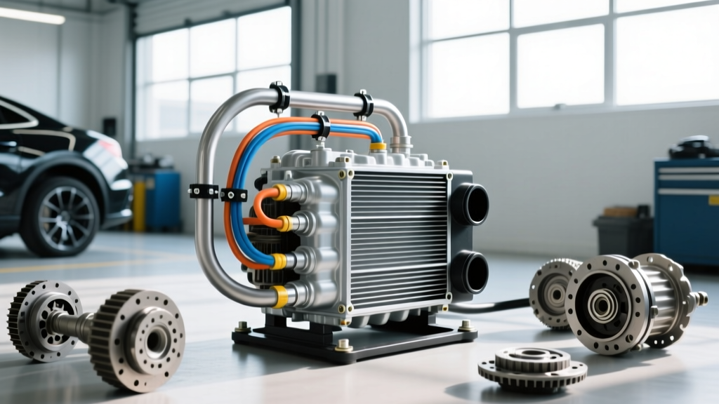
Most universal coolers, such as the popular Hayden 678 Rapid-Cool or the Derale 13503 Series 8000, come with nylon zip-ties and plastic spacer tubes. Never push a zip-tie directly through your vehicle's AC condenser or radiator fins without the spacer tube. If the zip-tie bends inside the fin stack, it can easily puncture an AC micro-channel, turning a $150 cooler install into an $800 AC repair. Mount the cooler as high and as centered as possible behind the grille, ensuring it does not block the factory cooling fan shroud.
Step 2: Cutting and Flaring the Lines
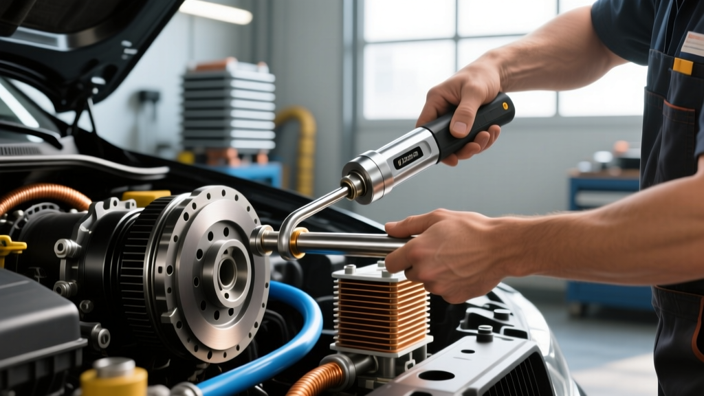
Once you have identified and marked the Return line, place a drain pan underneath. Use your mini tube cutter to make a clean, square cut in the metal line. If your vehicle uses rubber hose connected to barbed metal fittings, simply loosen the factory constant-tension clamp using a specialized clamp plier. Slide the new SAE J1019 hose over the barbed fitting. Ensure the hose is pushed completely down to the base of the barb, then secure it with a new fuel-injection style clamp, tightening it precisely to 15-20 in-lbs to prevent cutting into the rubber.
Step 3: Routing the Transmission Cooler Lines
Routing the new rubber hoses requires careful planning to avoid heat and moving parts. Follow these strict clearance rules:
- Exhaust Clearance: Maintain a minimum of 4 inches of clearance from exhaust manifolds, catalytic converters, and mufflers.
- Suspension Clearance: Zip-tie the lines securely to the frame rail. Ensure there is enough slack for the engine to rock under heavy acceleration and for the suspension to fully articulate off-road.
- Bend Radius: Do not kink the rubber hose. Maintain a minimum bend radius of 2 inches to prevent internal flow restriction.
Modern Transmissions and the Thermal Bypass Valve
If you are driving a modern vehicle equipped with a ZF 8HP (found in Ram, Jeep, BMW, and Jaguar) or a GM 8L90/10L90, you must understand the thermal bypass valve. Modern transmissions operate best at a specific temperature window (usually 180°F to 200°F). When the fluid is cold, a wax-element or electronic bypass valve prevents fluid from going to the cooler, forcing it to warm up quickly to reduce parasitic drag and emissions.
Pro-Tip for 2026 Towing Setups: If you install a massive auxiliary cooler without a thermostatic bypass sandwich plate (like the Derale 13540), your transmission may never reach operating temperature during winter or light-duty driving. Running ATF too cold prevents the torque converter clutch from locking up smoothly, leading to shudder and premature wear. Always retain the factory radiator loop or install an inline thermostatic bypass.
Bleeding the System and Checking Fluid Levels
Adding an auxiliary cooler and extending the transmission cooler lines will introduce air into the system and require additional fluid. A standard plate-and-fin cooler holds between 0.5 and 1.5 quarts of fluid.
- GM 6L80 / 8L90: These feature a traditional dipstick (or a fill plug on the pan for the 8-speed). Add fluid until it registers on the dipstick, then run the engine through all gears with the brake applied to purge air from the cooler circuit. Recheck the level with the fluid between 86°F and 122°F (30°C-50°C).
- ZF 8HP: This transmission has no dipstick. It requires a strict temperature-dependent level check. You must plug in an OBD2 scan tool to monitor the transmission pan temperature. With the engine idling and the transmission at exactly 40°C (104°F), remove the 8mm Allen fill plug on the bottom of the pan. Fluid should drip out in a steady stream. If it doesn't, pump in ATF until it does, then reinstall the plug and torque to 25 Nm (18 ft-lbs).
Final Thoughts on Thermal Management
Properly routing your transmission cooler lines is about respecting the hydraulic boundaries of your drivetrain. By tapping into the return line, using ATF-rated SAE J1019 hose, and respecting the thermal bypass parameters of modern 8- and 10-speed transmissions, you will drop your peak towing temperatures by 30°F to 50°F. For further reading on thermal dynamics and OEM bypass specifications, consult resources like Hayden Auto's technical library or the engineering archives at Transmission Digest. Take your time, double-check your fittings, and enjoy the peace of mind that comes with bulletproof transmission cooling.