Introduction to Modern Drivetrain Precision
Setting up a ring and pinion gear set has always been considered a dark art in the automotive world. For decades, mechanics relied on brass shims, yellow ochre marking compounds, and a trained ear to achieve the perfect gear mesh. However, as we navigate the automotive landscape of 2026, the introduction of electronically controlled limited-slip differentials has added a complex layer of digital diagnostics to this mechanical process. When rebuilding or regearing modern performance axles, understanding the relationship between your physical gear mesh and the active differential probe is no longer optional—it is critical to the survival of your drivetrain.
This beginner-friendly explainer will bridge the gap between old-school mechanical wrenching and modern electronic calibration. We will walk through the exact steps required to set up a ring and pinion, verify gear patterns, and properly calibrate the active differential probe to ensure your vehicle's traction control ECU receives flawless data.
Demystifying the Active Differential
Before we can discuss the probe, we must understand the differential it monitors. Unlike a traditional mechanical limited-slip differential (LSD) that uses spring-loaded clutch packs or helical gears (like a Torsen unit) to distribute torque, an active differential utilizes an electronically controlled, multi-plate wet clutch pack. Examples include the BMW Active M Differential found in the G80 M3, the Audi Sport Differential, and the electronic locking units in modern Ford Performance axles.
These systems rely on wheel speed sensors, steering angle inputs, and throttle position to micro-manage torque distribution in milliseconds. If the physical ring and pinion setup is flawed, or if the sensor monitoring the carrier speed is misaligned, the ECU will detect a discrepancy between the wheel speed sensors and the internal carrier speed. This immediately triggers a failsafe mode, reverting the vehicle to an open differential and illuminating the dashboard with chassis and ABS fault codes.
What is an Active Differential Probe?
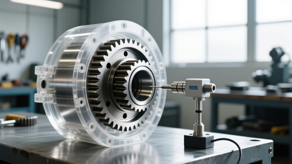
The active differential probe (often referred to as the internal carrier speed sensor or inductive reluctor probe) is the electronic 'eye' that monitors the rotational speed of the differential carrier and the internal clutch pack slip. In many modern active differentials, this probe reads a reluctor ring (a toothed or magnetic encoder ring) that is either pressed onto the ring gear carrier or integrated directly into the ring gear itself.
When you perform a ring and pinion setup, you are adjusting the physical position of the carrier via shims to achieve the correct gear backlash and tooth contact pattern. Moving the carrier left or right to achieve your backlash specification inherently changes the air gap between the reluctor ring and the active differential probe. If this air gap falls outside the strict factory tolerance—typically between 0.5mm and 1.2mm—the probe will read erratic signals, especially under heavy axle deflection or high-temperature fluid expansion.
Essential Tools and Torque Specifications
To achieve a factory-grade setup, you must abandon the 'tighten it until it stops' mentality. Precision measurement tools are mandatory. Below is a reference table for a typical modern independent rear suspension (IRS) active differential setup, such as the Audi C8 Sport Differential or BMW G-Series Active M unit.
| Component / Measurement | Target Specification | Required Tooling |
|---|---|---|
| Pinion Bearing Preload | 14 - 18 in-lbs (New Bearings) | Inch-pound dial torque wrench (0-30 in-lbs) |
| Ring Gear Backlash | 0.10mm - 0.15mm (0.004 - 0.006 in) | Magnetic base dial indicator (0.01mm resolution) |
| Active Probe Air Gap | 0.6mm - 1.0mm | Non-magnetic brass feeler gauge set |
| Ring Gear Bolt Torque | 65 Nm + 90° (Yield Bolts) | Digital torque angle wrench |
| Pinion Nut Torque (Solid Spacer) | 280 - 320 Nm | Heavy-duty 1/2" drive torque wrench |
Step-by-Step Ring and Pinion Setup
Setting up the gears requires patience. You will likely assemble and disassemble the carrier multiple times to get the shimming correct. According to setup guidelines from Yukon Gear & Axle, cleanliness and precise measurement are your best friends during this process.
1. Pinion Depth and Bearing Preload
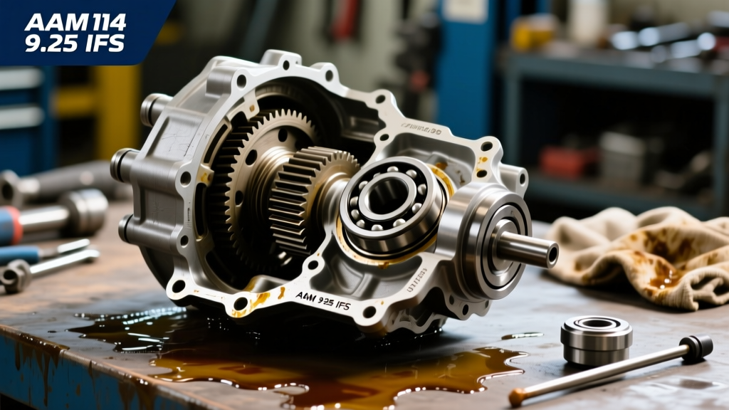
The pinion depth dictates how deeply the pinion gear meshes into the ring gear. This is adjusted using shims located between the pinion head bearing and the differential housing. A pinion that is too deep will cause the gear pattern to run off the toe of the tooth, leading to catastrophic edge-loading and gear whine. Once the depth is established via the marking compound pattern, you must set the pinion bearing preload.
Modern setups highly recommend using a solid pinion spacer kit rather than a traditional crush sleeve. Crush sleeves are notorious for losing preload over time as the metal fatigues, leading to pinion bearing failure. With a solid spacer and shims, you can torque the pinion nut to a massive 300 Nm and use your inch-pound dial torque wrench to verify that the rolling resistance (preload) sits perfectly at 16 in-lbs.
2. Carrier Shimming and Backlash
With the pinion installed, it is time to mount the ring gear to the carrier. Always use new, high-strength ring gear bolts. Apply a medium-strength threadlocker (like Loctite 243) and torque them in a star pattern to the yield specification (e.g., 65 Nm plus an additional 90-degree turn).
Install the carrier into the housing with your initial guess for the side shims. Mount your magnetic dial indicator so the plunger is perfectly perpendicular to the face of a ring gear tooth. Rock the ring gear back and forth while holding the pinion flange stationary. You are looking for 0.12mm of backlash. If the backlash is too tight, you must move the carrier away from the pinion by increasing the shim on the opposite side and decreasing the shim on the ring gear side. Remember: every time you adjust the side shims to change backlash, you are also moving the reluctor ring relative to the active differential probe.
3. Active Probe Sensor Gap Verification
This is the step most traditional mechanics miss. Once your backlash and gear pattern are perfect, you must verify the active differential probe air gap. Insert a non-magnetic brass feeler gauge between the tip of the probe and the reluctor ring. Rotate the carrier a full 360 degrees to check for runout. If the ring gear carrier has excessive lateral runout (more than 0.05mm), the air gap will fluctuate wildly as the differential spins, causing the ECU to register intermittent speed sensor dropouts. If the runout is out of spec, you must check the ring gear mounting surface for debris or replace the carrier assembly.
Reading the Gear Contact Pattern
Numbers on a dial indicator only tell half the story. You must verify the physical mesh using a high-contrast gear marking compound. Apply a thin, even coat of yellow ochre to the drive side of the ring gear teeth, and red lead to the coast side. Apply a slight drag to the ring gear (using a gloved hand or a brake caliper tool) and rotate the pinion through several full revolutions.
- Ideal Pattern: The marking should be centered vertically on the tooth face and slightly biased toward the toe (the inner edge of the ring gear). Under load, the pattern will naturally shift toward the heel.
- Too Deep (Pinion): The pattern runs heavily on the toe and bottom flank. Solution: Decrease pinion depth shim.
- Too Shallow (Pinion): The pattern runs on the heel and top flank. Solution: Increase pinion depth shim.
- Face/Flank Bias: If the pattern is too high on the face or too low on the flank, this is primarily corrected by adjusting the carrier side shims (backlash), not the pinion depth.
Common Beginner Mistakes to Avoid
When dealing with active differentials, the margin for error is razor-thin. Avoid these common pitfalls:
- Reusing Old Bearings: Never attempt to set pinion depth or preload using worn bearings. The internal clearances of a used tapered roller bearing will give you false dial indicator readings, resulting in a noisy differential once new bearings are pressed on.
- Ignoring the Reluctor Ring: If your active differential uses a press-on magnetic encoder ring, ensure it is seated perfectly square. A cocked encoder ring will destroy the active differential probe tip upon first startup.
- Skipping the Break-In Fluid Change: This is the most critical maintenance step for gear longevity.
Fluid Selection and the 500-Mile Break-In
The type of differential fluid you use is just as important as the physical gear setup. Because active differentials contain electronic clutch packs, you cannot simply dump in any off-the-shelf gear oil. The friction modifiers in the fluid are specifically calibrated to allow the clutch packs to slip and lock without shuddering or burning up. For example, Audi requires G 052 145 S2 fluid for their Sport Differential, while BMW specifies SAF-XJ 75W-140. For high-performance aftermarket builds, Motul Gear 300 75W-90 is a premier choice, provided the correct limited-slip friction modifier is added in the exact percentage required by the active clutch pack manufacturer.
When new ring and pinion gears mesh for the first time, they undergo a process called lapping. This generates immense heat and sheds microscopic metallic particulates into the fluid. If left in the housing, these metallic shards will embed themselves into the soft friction material of the active differential clutch packs, permanently ruining them. Furthermore, metallic debris can coat the tip of the active differential probe, insulating it and causing weak magnetic signal readings.
The Break-In Procedure:
- Fill the differential to the exact factory capacity (usually between 1.0L and 1.5L depending on the housing).
- Drive the vehicle for 15-20 miles at varying speeds (30 to 50 mph) to heat the fluid and allow the gears to lap.
- Let the differential cool completely to ambient temperature.
- Drain the fluid immediately. You will notice a glittery, metallic sheen—this is normal for a new gear set.
- Clean the magnetic drain plug thoroughly, refill with fresh, specified active differential fluid, and reset the ECU adaptation values using a bi-directional scan tool.
Conclusion
Mastering the ring and pinion setup on a modern axle requires a hybrid mindset. You must respect the mechanical fundamentals of gear geometry, bearing preload, and tooth contact patterns, while simultaneously respecting the digital requirements of the active differential probe. By utilizing precision measurement tools, adhering strictly to torque angle specifications, and following a rigorous fluid break-in protocol, you can build an axle that is whisper-quiet, mechanically bulletproof, and electronically seamless. For further reading on drivetrain component sourcing and technical data sheets, Dana Spicer remains an invaluable resource for both professional builders and dedicated enthusiasts.