Introduction: The Anatomy of Accessory Clutch Engagement
Welcome to Autogear Nexus. While our core expertise lies in automatic and manual transmission drivetrains, the fundamental physics of clutch engagement apply across the entire vehicle. As of 2026, modern EVs and hybrids largely utilize electrically driven, clutchless variable-displacement compressors. However, the traditional belt-driven electromagnetic AC clutch remains a staple in millions of internal combustion engine (ICE) vehicles and light-duty trucks on the road today.
When your cabin air turns warm and you hear the engine rev without the familiar 'click' of the AC compressor kicking in, you are likely facing clutch engagement and disengagement issues. This beginner-friendly explainer will demystify how these clutches work, how to diagnose engagement failures, and the step-by-step process of replacing clutch on AC compressor assemblies without draining your wallet or your refrigerant.
Why Won't It Engage? Diagnosing the AC Compressor Clutch
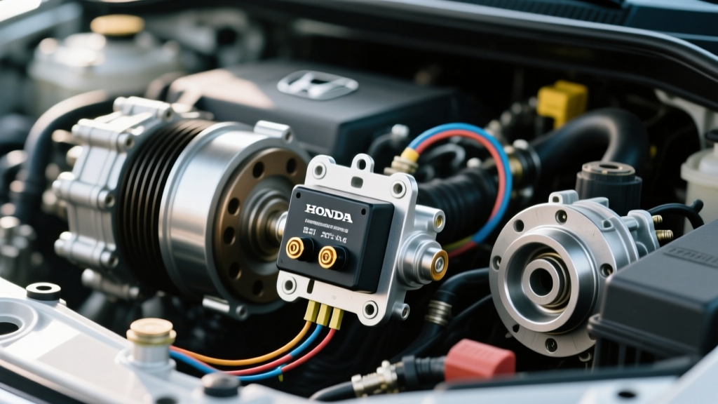
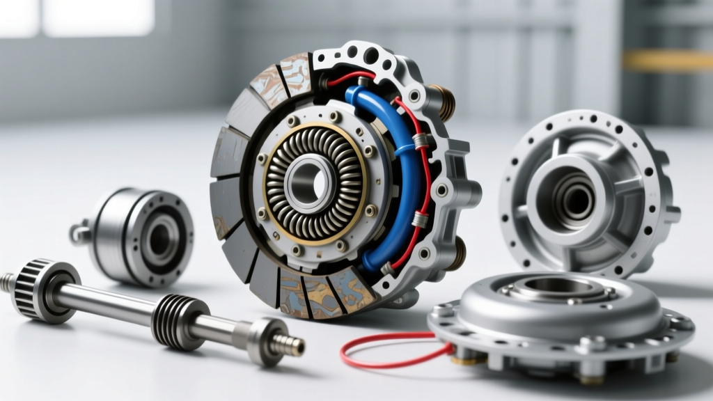
Unlike the hydraulic clutch packs found inside a transmission, the AC compressor clutch is an electromagnetic device. When the climate control system calls for cooling, a 12-volt signal is sent to an electromagnetic coil mounted on the compressor. This creates a magnetic field that pulls the front friction plate (the hub) against the spinning pulley rotor, locking them together to turn the compressor shaft.
When engagement fails, the issue typically falls into one of three categories: electrical failure, mechanical air gap issues, or system pressure safeties.
Step 1: The Electrical Path and Coil Resistance
Before turning a single wrench, you must verify the electrical signal. Using a digital multimeter, check for 12 volts at the clutch connector with the engine running and AC set to maximum. If you have 12 volts but the clutch isn't pulling in, the coil is likely dead.
To confirm, unplug the connector and measure the resistance (Ohms) across the clutch coil terminals. According to AA1Car's AC Clutch Diagnostic Guide, a healthy electromagnetic coil should read between 3.0 and 5.0 ohms at room temperature (68°F/20°C).
- Infinite Resistance (OL): The coil has an internal open circuit. Replacement is required.
- Near Zero Resistance: The coil is shorted internally and will blow the AC fuse.
Step 2: Mechanical Air Gap Verification
If the coil is energizing (you can feel it get warm or measure the correct resistance) but the clutch is slipping or failing to pull in, your air gap is likely out of specification. The air gap is the physical distance between the friction plate and the pulley rotor when disengaged.
Over time, the friction material on the plate wears down, widening this gap. If the gap exceeds 0.040 inches (1.0 mm), the electromagnet is no longer strong enough to bridge the distance and pull the plate in. You can measure this using a standard automotive feeler gauge. The ideal specification for most Denso and Sanden compressors is between 0.020" and 0.030" (0.5mm - 0.75mm).
Disengagement Failures: When the Clutch Stays Locked
While failure to engage is common, failure to disengage is a critical safety hazard. If the AC clutch remains locked to the pulley when the AC is turned off, it can cause severe belt wear, overheating, and eventual compressor seizure.
Disengagement issues are rarely caused by the clutch itself. Instead, they are usually the result of:
- Welded Relay Contacts: The AC compressor relay in the under-hood fuse box has internally fused, sending constant 12V power to the coil.
- Short to Ground/Power: Frayed wiring in the harness is bypassing the control module.
- Mechanical Binding: Rust, debris, or a warped friction plate is physically wedging the hub against the pulley even when the magnetic field is removed.
Drivetrain Contrast: AC Electromagnetic vs. Transmission Hydraulic Clutches
To truly understand clutch diagnostics, it helps to compare the accessory drive clutch to the internal clutch packs of an automatic transmission. While both serve to transfer rotational power, their actuation methods and failure modes are vastly different. Below is a comparison between a standard AC clutch and the 3-5-R clutch pack found in the ubiquitous GM 6L80 transmission.
| Diagnostic Feature | AC Compressor Electromagnetic Clutch | GM 6L80 Transmission Clutch Pack (3-5-R) |
|---|---|---|
| Actuation Method | 12V Electromagnetic Coil | Hydraulic Fluid Pressure via Solenoid |
| Engagement Medium | Magnetic pull on steel friction plate | Piston compressing alternating friction/steel plates |
| Typical Failure Mode | Widened air gap or burnt coil | Torn piston seal or glazed friction material |
| Primary Diagnostic Tool | Multimeter and Feeler Gauge | Transmission Pressure Gauge and Scan Tool |
| Average Replacement Cost | $45 - $150 (Clutch Kit Only) | $1,800 - $2,800 (Transmission Rebuild) |
As noted by Sonnax Transmission Tech Resources, when a transmission clutch pack fails to engage, the root cause is often a microscopic tear in the apply piston seal or a stuck pressure control solenoid, requiring a complete teardown. Conversely, an AC clutch can often be serviced externally, making it a highly approachable repair for beginners.
Step-by-Step: Replacing Clutch on AC Compressor
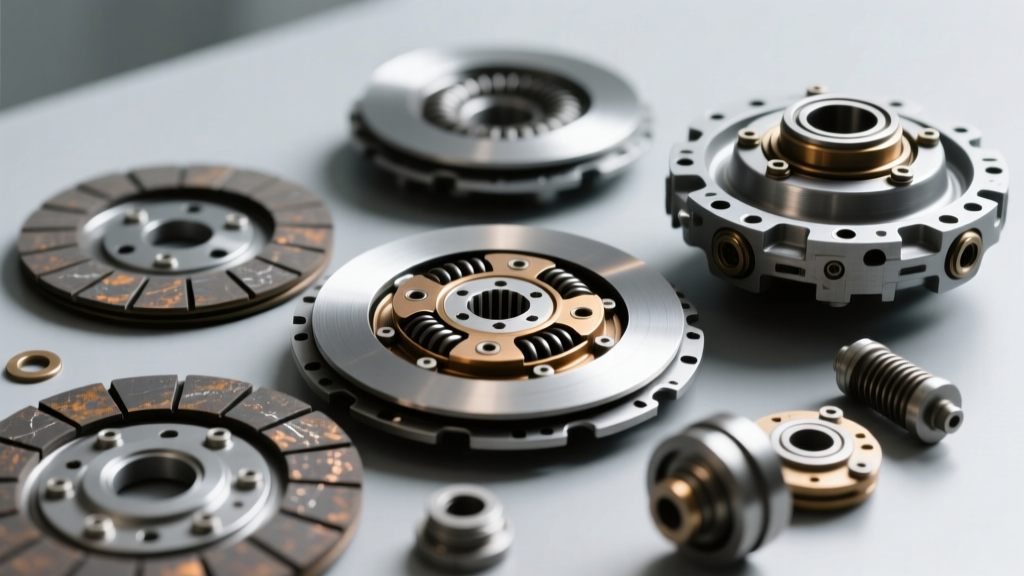
If your diagnostics confirm a bad coil or severely worn friction plate, you will need to replace the clutch assembly. Fortunately, on many vehicles, this can be done without evacuating the refrigerant system, provided you have enough physical clearance to work in the engine bay. For detailed vehicle-specific routing, NAPA Know How offers excellent model-year specific visual guides.
Tools Required
- AC Clutch Puller/Installer Tool Kit (specific to your compressor model)
- Internal/External Snap Ring Pliers
- Feeler Gauge Set
- Torque Wrench (inch-pounds capable)
The Replacement Procedure
- Remove the Center Bolt: Use the appropriate socket (often 6mm, 8mm, or 10mm) to remove the center bolt securing the friction plate. Pro-Tip: If the plate is stuck, thread the bolt back in a few turns and tap it gently with a brass drift to pop the plate off the splined shaft.
- Pull the Friction Plate: Slide the plate off. Note the location and quantity of the thin metal shims on the shaft. These dictate your air gap; do not lose them.
- Remove the Pulley Rotor: Use your external snap ring pliers to remove the large snap ring holding the pulley bearing to the compressor snout. Slide the pulley off.
- Swap the Electromagnetic Coil: Remove the internal snap ring securing the coil. Disconnect the wiring pigtail, slide the old coil off, and slide the new one on. Ensure the anti-rotation tab on the coil aligns with the notch in the compressor housing. Reinstall the snap ring.
- Reassemble and Set the Air Gap: Slide the pulley back on and secure it with its snap ring. Place your original shims back on the shaft, followed by the new friction plate. Press the plate down firmly.
- Measure and Adjust: Use your feeler gauge to check the gap at 3 or 4 points around the circumference. If the gap is wider than 0.030", remove a shim. If it's tighter than 0.020", add a shim. An incorrect gap will result in immediate slipping or premature bearing failure.
- Torque the Center Bolt: Reinstall the center bolt. The standard torque specification for most compressor hub bolts is 10 to 15 Nm (7 to 11 lb-ft). Do not overtighten, as you can strip the threads on the compressor shaft.
Final Diagnostic Takeaways
Clutch engagement and disengagement issues can feel overwhelming to a beginner, but they follow a strict logical path. By isolating the electrical circuit, verifying the mechanical air gap, and understanding the difference between electromagnetic accessory clutches and hydraulic transmission clutches, you can accurately diagnose the failure. Replacing the clutch on an AC compressor is a highly rewarding, cost-effective repair that restores cabin comfort and saves you from an unnecessary full-compressor replacement.