The Symbiosis of PRNDL and Speed Sensor Data in Modern TCMs
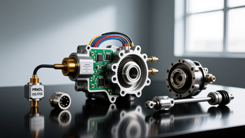
As automotive transmissions have evolved into highly complex electro-mechanical systems, the Transmission Control Module (TCM) has become entirely dependent on a delicate web of sensor inputs. Two of the most critical data streams governing shift quality, line pressure, and torque converter clutch (TCC) application are the Transmission Range (TR) sensor and the Input/Output Speed Sensors (ISS/OSS). In 2026, with the proliferation of 8-speed, 9-speed, and 10-speed automatic transmissions like the Ford 10R80, GM 10L90, and ZF 8HP, diagnosing electronic faults requires a systematic understanding of how these sensors interact.
Frequently, technicians encounter a diagnostic trouble code (DTC) with the generic scan tool description transmission range sensor a circuit prndl input (commonly associated with P0705 or P0706). While the immediate instinct might be to replace the neutral safety switch or recalibrate the shift linkage, a PRNDL input fault can often mask—or be directly caused by—underlying speed sensor circuit failures. When the TCM cannot verify the physical gear selected via the PRNDL switch, it defaults to a fail-safe limp mode (often locking the transmission in 2nd or 3rd gear) and maximizes line pressure. In this state, the TCM may simultaneously flag irrational speed sensor codes (such as P0717 for Input Speed Sensor Circuit No Signal or P0720 for Output Speed Sensor Circuit) simply because the vehicle's speed does not correlate with the default gear ratio. Mastering transmission speed sensor diagnosis and replacement requires first understanding this diagnostic hierarchy.
Diagnostic Hierarchy: Isolating the Root Cause
Before condemning a speed sensor or tearing into the transmission pan, you must verify the integrity of the PRNDL circuit. The TCM uses the PRNDL input to dictate base line pressure and enable specific shift solenoids. If the transmission range sensor a circuit prndl input signal is floating or shorted to ground, the TCM will inhibit TCC lockup and ignore ISS/OSS data for shift scheduling.
Step 1: Verify PRNDL Voltage Drops
Using a high-impedance digital multimeter (DMM), back-probe the TR sensor signal circuit at the TCM connector. Most modern Hall-effect TR sensors utilize a 5-volt reference, a low-reference ground, and multiple signal return wires (often A, B, C, and P circuits) that create a unique binary or Gray-code voltage pattern for Park, Reverse, Neutral, Drive, and Low. If your scan tool displays a PRNDL fault, but the physical linkage is tight, check for connector fretting—a common issue in 2018-2024 GM 6L80 and 8L90 transmissions where micro-vibrations cause terminal oxidation. According to Sonnax Transmission Specialties, applying a high-quality dielectric compound and ensuring terminal tension can resolve intermittent PRNDL and speed sensor dropouts without replacing the entire harness.
Deep Dive: Transmission Speed Sensor Diagnosis
Once the PRNDL circuit is verified as healthy, attention must shift to the speed sensors. Modern transmissions primarily use two types of speed sensors: Variable Reluctance (VR) and Hall-Effect. Misidentifying the sensor type is the most common cause of misdiagnosis.
Variable Reluctance (VR) Sensors
Found predominantly in older designs like the GM 4L60E and early Ford 4R70W, VR sensors are essentially magnetic pickups. They generate an Alternating Current (AC) sine wave whose amplitude and frequency increase with rotational speed.
- Testing Method: Set your DMM to AC Volts. Spin the drive wheels (with the vehicle safely lifted and in neutral). You should see a minimum of 0.5V AC at idle speeds, climbing to 3.0V+ at highway speeds.
- Resistance Check: Disconnect the sensor and measure resistance across the two pins. Typical specifications range from 1,400 to 2,500 ohms at room temperature. An open circuit (OL) or a short to ground indicates internal coil failure.
Hall-Effect Sensors
Virtually all modern transmissions (ZF 8HP, GM 10L90, Toyota Direct Shift 8AT) utilize Hall-effect sensors. These require an external power source (usually 5V to 12V from the TCM) and output a digital square wave.
- The Oscilloscope Advantage: A DMM is insufficient for diagnosing Hall-effect dropouts. You must use an oscilloscope to view the square wave. A healthy sensor will show a crisp, flat-topped 5V or 12V square wave. Rounded edges, voltage sag, or 'dropped frames' (missing teeth signals) indicate a failing sensor, a damaged reluctor ring, or excessive metallic debris on the sensor's magnetic tip.
- Power and Ground Verification: Before replacing the sensor, verify the 5V reference and ground at the harness connector. A voltage drop on the 5V reference line (e.g., reading 4.2V) will cause the sensor to output a weak signal, triggering a P0715 (Input/Turbine Speed Sensor Circuit) code.
Sensor Diagnostics & Application Matrix
The following table outlines common transmission applications, sensor types, and diagnostic baselines for 2026 workshop reference.
| Transmission Model | Sensor Type | Reference / Signal | Common DTCs | Typical OEM Part Cost |
|---|---|---|---|---|
| GM 4L60E (OSS) | Variable Reluctance | AC Sine Wave (Self-generating) | P0720, P0722 | $25 - $45 |
| GM 6L80 (ISS/Turbine) | Hall-Effect | 5V Ref / Digital Square Wave | P0715, P0717 | $85 - $130 |
| ZF 8HP45/70 (Output) | Hall-Effect | 12V Ref / Digital Square Wave | P0720, P0721 | $90 - $150 |
| Ford 10R80 (OSS) | Hall-Effect | 5V Ref / Digital Square Wave | P0720, P0722 | $110 - $160 |
Mechanical Replacement & Torque Specifications
Replacing a speed sensor is rarely as simple as unbolting it and plugging in a new one. Proper installation requires strict adherence to torque specifications and O-ring preparation to prevent catastrophic fluid leaks or internal pressure loss.
GM 4L60E / 4L80E Output Speed Sensor (OSS)
The OSS on these units is located in the extension housing (tail housing).
- Removal: Remove the 10mm retaining bolt. If the sensor is seized due to aluminum oxidation, do not pry it with a screwdriver, as this will score the extension housing bore. Apply penetrating fluid and twist gently with pliers on the sensor body.
- Preparation: Lubricate the new O-ring with the exact ATF specified for the unit (e.g., Dexron VI). Never use petroleum jelly, which can swell and degrade transmission elastomers.
- Torque Spec: The 10mm retaining bolt must be torqued to 11 Nm (97 lb-in). Over-torquing can crack the sensor's plastic housing, leading to delayed fluid leaks.
ZF 8HP Mechatronic Sleeve & Internal Sensors
On the ZF 8HP series, the input and output speed sensors are often integrated directly into the Mechatronic unit or the rear output housing, depending on the generation. If replacing the rear output speed sensor on a Gen 1 ZF 8HP:
- Torque Spec: The T25 Torx retaining bolt requires exactly 8 Nm (71 lb-in).
- Fluid Consideration: You will lose a significant amount of ZF LifeguardFluid 8. The ZF 8HP has no traditional dipstick; it requires a temperature-dependent leveling procedure using a scan tool to monitor the fluid pan temperature (must be between 30°C and 50°C) while the engine is idling. Failing to perform this leveling procedure will result in low fluid volume, causing immediate TCC shudder and pump cavitation.
TCM Adaptations and The Relearn Imperative
A critical step that separates novice mechanics from seasoned transmission experts is the post-replacement relearn procedure. When you replace an ISS or OSS, or even clear a transmission range sensor a circuit prndl input code, the TCM's adaptive memory may still hold shift volume and pressure data calibrated to the previous faulty state.
Expert Insight: 'Never hand the keys back to the customer immediately after clearing a P0717 or P0705 code. The TCM must undergo a Fast Adaptation reset via a bidirectional scan tool, followed by a specific drive cycle. For GM 10-speed units, this requires performing 10 consecutive part-throttle upshifts and downshifts between 20 mph and 50 mph to allow the TCM to relearn the clutch fill volumes based on the new, accurate speed sensor data.'
Wiring Harness Chafing: The Hidden Culprit
If you have verified the sensor, confirmed the 5V reference, and the PRNDL switch is functioning perfectly, the fault likely lies in the wiring harness. In vehicles like the 2015-2022 Ford F-150 with the 10R80, the internal transmission wiring harness is notorious for chafing against the valve body casting near the ISS connector. The constant vibration and thermal cycling cause the insulation to wear through, shorting the speed sensor signal to the 12V solenoid circuits.
When diagnosing, always perform a wiggle test on the internal harness while monitoring the ISS PID on your scan tool. If the RPM data drops out while wiggling the harness near the valve body, the internal harness must be replaced. According to SAE International J1979 standards regarding OBD-II data link reporting, intermittent signal dropouts that occur for less than 2 seconds may not immediately set a hard DTC, but will cause the TCM to abort shift commands, resulting in the harsh 'flare' or 'tie-up' shifts commonly misdiagnosed as mechanical clutch failures.
Summary of Best Practices
Diagnosing transmission electronics in 2026 requires moving beyond simple resistance checks. By understanding the interplay between the PRNDL input circuit and the ISS/OSS data streams, utilizing an oscilloscope for Hall-effect waveform analysis, and strictly adhering to OEM torque and fluid leveling procedures, you can accurately resolve complex drivability complaints on the first visit. Always remember: a speed sensor code is often a symptom of a reference voltage issue, a harness chafe, or a limp-mode cascade triggered by a seemingly unrelated range sensor fault.