Diagnosing Electronic Shift Faults in Heavy-Duty Drivetrains
Modern heavy-duty and medium-duty transmissions rely on a complex symphony of electronic actuators and sensors to manage shift timing, line pressure, and torque converter lockup. When an Allison 1000 or 2000 series transmission enters limp mode or exhibits erratic shifting, the root cause is frequently traced back to the valve body's electro-hydraulic controls. However, as of 2026, advanced diagnostic protocols require technicians to look at the entire electronic ecosystem. Before condemning the internal shift solenoids, it is vital to verify rotational input data, which brings the allison transmission speed sensor location into the diagnostic spotlight.
This comprehensive guide will walk you through pinpointing sensor locations, identifying shift solenoid problems, and executing a precision step-by-step shift solenoid replacement procedure on Allison 1000 and 2000 series platforms commonly paired with heavy-duty diesel applications.
Mapping the Allison Transmission Speed Sensor Location vs. Solenoids
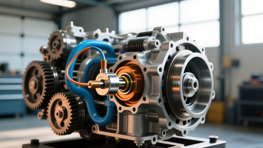
When a commercial truck or heavy-duty pickup enters limp mode, technicians must cross-reference solenoid data with rotational inputs, making the allison transmission speed sensor location a primary checkpoint before dropping the transmission pan. If the Transmission Control Module (TCM) cannot accurately read the input and output shaft speeds, it will inhibit solenoid actuation to protect the clutch packs from catastrophic slip-burn.
- Input Speed Sensor (ISS): Located on the main transmission case, typically near the bellhousing area, reading the reluctor ring on the input shaft or torque converter hub.
- Output Speed Sensor (OSS): Located on the rear extension housing or tail shaft, monitoring the final drive speed before the yoke or flange.
- Shift Solenoids: Housed entirely inside the transmission fluid pan, mounted directly to the valve body assembly or integrated into the Transmission Electronic Control Hybrid Module (TEHCM) on newer generations.
Because the speed sensors are external, they can be tested and replaced without draining the transmission fluid. Always verify the ISS and OSS signals using an oscilloscope or advanced scan tool before assuming the internal shift solenoids have failed.
Common Shift Solenoid Problems and Diagnostic Codes
Shift solenoids are electro-mechanical valves that direct hydraulic fluid to specific clutch packs. Over time, normal clutch wear generates microscopic metallic and friction material debris. Even with a high-capacity filter, this debris can clog the tiny mesh screens on the solenoid feed tubes, causing them to stick open or closed.
Below are the most frequent OBD-II and manufacturer-specific diagnostic trouble codes (DTCs) associated with solenoid failure:
| DTC | Description | Typical Failure Mode |
|---|---|---|
| P0750 | Shift Solenoid 'A' Malfunction | Open circuit, short to ground, or mechanically stuck valve. |
| P0755 | Shift Solenoid 'B' Malfunction | Clogged feed screen preventing hydraulic actuation. |
| P0770 | Shift Solenoid 'C' Malfunction | PWM solenoid coil degradation due to excessive heat. |
| P0776 | Pressure Control Solenoid 'B' Stuck Off | Debris wedged in the solenoid exhaust port. |
For deeper code analysis, referencing resources like OBD-Codes.com can help differentiate between electrical circuit faults and hydraulic performance issues. If your scan tool shows the commanded gear does not match the actual gear ratio calculated via the speed sensors, you are likely dealing with a stuck solenoid or a cross-leaking valve body bore.
Electrical Bench Testing: Solenoids vs. Speed Sensors
Before tearing into the transmission pan, perform a resistance check at the external transmission wiring harness connector.
Testing Shift Solenoids
Allison transmissions utilize both On/Off solenoids and Pulse Width Modulated (PWM) solenoids. Using a digital multimeter set to Ohms:
- On/Off Solenoids: Expect a resistance reading between 10 and 14 ohms at room temperature.
- PWM / Pressure Control Solenoids: Expect a lower resistance, typically between 4.0 and 6.5 ohms.
If a solenoid reads infinite resistance (OL), the internal coil is broken, mandating a replacement.
Testing Hall-Effect Speed Sensors
The speed sensors require a 5-volt reference, a clean ground, and a signal return circuit. Back-probe the sensor connector with the key on, engine off. You should read 5V on the reference wire. If the wiring harness is intact but the sensor outputs no square-wave frequency signal while the driveline is rotated, the sensor has failed internally.
Step-by-Step Shift Solenoid Replacement Guide
If electrical testing confirms a failed internal solenoid, or if hydraulic debris has permanently fouled the unit, a replacement is required. This procedure outlines the service for a standard rear-wheel-drive Allison 1000/2000 series configuration.
Step 1: Preparation and Fluid Drain
Raise the vehicle on a professional-grade lift and ensure it is securely supported. Place a high-capacity drain pan beneath the transmission. Remove the transmission pan bolts, leaving the two rear corner bolts loosely threaded to allow the pan to pivot and drain the fluid safely. As of 2026, the industry standard for these units is Allison TES 668 synthetic fluid, which offers superior thermal stability compared to older TES 295 formulations.
Step 2: Filter and Harness Removal
Once drained, remove the pan entirely. The internal spin-on or push-in filter (Part # 29543204 for most deep-pan applications) must be discarded. Carefully disconnect the internal wiring harness connectors from the solenoid pack and the internal temperature sensor. Note the routing of the harness to avoid pinch-points during reassembly.
Step 3: Solenoid Pack Extraction
Depending on your exact generation, the solenoids may be part of a monolithic valve body assembly or a separate solenoid pack bolted to the valve body. Remove the retaining bolts securing the solenoid pack to the valve body. Gently twist and pull the solenoid assembly outward. Caution: Do not use metal pry bars, as scoring the aluminum valve body mating surface will cause permanent hydraulic cross-leaks.
Step 4: Cleaning and Installation
Clean the valve body mating surface with lint-free shop towels and a non-chlorinated brake cleaner. Lubricate the new solenoid pack's O-rings and feed tubes with fresh TES 668 transmission fluid. Seat the new solenoid pack firmly into the valve body, ensuring all alignment dowels are fully engaged. Hand-start the retaining bolts to prevent cross-threading.
Allison 1000/2000 Series Torque Specifications and Parts Data
Precision torque is critical when reassembling hydraulic valve bodies. Overtightening can distort the aluminum castings, causing spool valves to bind in their bores.
| Component | Fastener Size / Type | Torque Specification | Part Number (Reference) |
|---|---|---|---|
| Solenoid Pack to Valve Body | M6 x 1.0 Bolts | 97 lb-in (11 Nm) | 29538289 (Pack) |
| Valve Body to Transmission Case | M8 / M10 Bolts | 11 lb-ft (15 Nm) | N/A |
| Transmission Pan to Case | M8 Flange Bolts | 18 lb-ft (24 Nm) | N/A |
| Internal Filter O-Ring | Push-In Seal | Hand Seat + Lube | 29543204 |
Post-Repair Calibration and Fluid Fill
Reinstall the transmission pan using a new gasket or high-temperature RTV silicone (if designed for a gasket-less seal). Torque the pan bolts in a crisscross pattern to 18 lb-ft.
Refill the transmission through the dipstick tube or fill plug with approximately 7 to 9 quarts of TES 668 fluid for a standard pan drain and fill. Start the engine, allow the fluid to reach normal operating temperature (160°F - 180°F), and cycle the gear selector through all positions, pausing for three seconds in each gear to bleed air from the clutch apply cavities.
Pro-Tip for 2026 Diagnostics: After replacing shift solenoids or the valve body, you must reset the TCM's shift adapt values. Using the Allison DOC (Diagnostic Optimization Center) software or a high-end bidirectional scan tool, clear the adapt cells. This forces the TCM to relearn the precise PWM duty cycles required for the new solenoids, preventing harsh 1-2 or 2-3 shifts during the first 50 miles of driving.
For further support on heavy-duty drivetrain calibration, technicians can consult the Allison Transmission Support Portal for the latest TCM flash files and service bulletins. By methodically verifying the speed sensors first and executing a clean, torque-spec-compliant solenoid replacement, you ensure the longevity and reliability of the transmission for hundreds of thousands of miles.