Decoding the P0841 Fault in VW DSG Mechatronic Units
When diagnosing a transmission fluid pressure sensor switch P0841 VW DSG fault, technicians and enthusiasts often rush to condemn the entire mechatronic unit. However, the P0841 code—specifically denoting 'Transmission Fluid Pressure Sensor/Switch A Circuit Range/Performance'—is fundamentally an electrical and hydraulic anomaly that requires a methodical, preventive maintenance-oriented troubleshooting approach. In Volkswagen and Audi vehicles equipped with the DQ250 (02E) 6-speed wet-clutch or the newer DQ381 7-speed wet-clutch Direct Shift Gearboxes, the mechatronic unit acts as the brain and the muscle. It houses the Transmission Control Module (TCM), solenoid valves, and critical pressure sensors directly inside the transmission fluid pan.
Understanding how to electrically troubleshoot this circuit before opting for a $2,500 mechatronic replacement is a hallmark of advanced transmission diagnostics. This guide explores the electrical architecture of the VW DSG pressure sensors, outlines precise oscilloscope and multimeter testing procedures, and establishes a preventive maintenance protocol to keep the mechatronic PCB and sensor diaphragms free from conductive contamination.
The Anatomy of P0841: What 'Range/Performance' Actually Means
The P0841 code does not necessarily mean the sensor is dead or that the circuit is completely open (which would trigger a P0840 'Circuit Malfunction' code). Instead, 'Range/Performance' indicates that the TCM is seeing a voltage signal from the pressure sensor that does not logically correlate with the physical hydraulic pressure being commanded by the PWM (Pulse Width Modulated) solenoids.
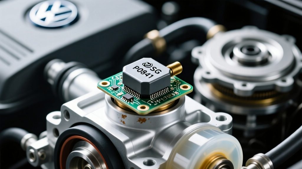
In the DQ250 02E transmission, the primary pressure sensors include the Main Line Pressure Sensor (G270) and the Clutch 1 and Clutch 2 Pressure Sensors (G193 and G194). These are typically piezoresistive sensors that receive a 5-volt reference from the TCM and return a variable signal voltage (usually between 0.5V and 4.5V) based on hydraulic pressure. If the sensor's internal diaphragm is fouled by clutch debris, or if the microscopic solder joints on the mechatronic flex-board suffer from thermal fatigue, the signal voltage will 'flatline' or spike erratically during clutch engagement, triggering the P0841 code and forcing the DSG into a protective limp mode (often locking the vehicle in 2nd or 3rd gear).
Electrical Troubleshooting Framework: Beyond the Code Scanner
Proper electrical troubleshooting of the DSG pressure sensor circuit requires moving past basic OBD2 scanners and utilizing a digital multimeter (DMM), a digital storage oscilloscope (DSO), and VAG-specific diagnostic software like VCDS (VAG-COM) or ODIS.
Step 1: VCDS Measuring Value Blocks (MVB) Analysis
Before unbolting a single mechatronic fastener, connect your VCDS interface and navigate to the Transmission Control Module (Address 02). Access the Measuring Value Blocks to compare commanded pressure versus actual sensed pressure. For the 02E DSG, check MVB Group 012 (Main Pressure), 013 (Clutch 1), and 014 (Clutch 2). If the commanded pressure ramps up smoothly but the actual sensed pressure shows a jagged, erratic graph or lags by more than 1.5 bar, you have isolated the issue to either a mechanical restriction in the valve body or a failing sensor element.
Step 2: The 5-Volt Reference and Ground Integrity Test
A common misdiagnosis involves replacing a sensor that is actually suffering from a poor ground. With the transmission harness disconnected at the TCM (located inside the mechatronic housing under the fluid), use a DMM to test the 5V reference circuit. You should read exactly 5.0V (+/- 0.1V) between the sensor reference pin and a known good chassis ground. Next, perform a voltage drop test on the sensor ground circuit. A voltage drop greater than 0.05V under load indicates corroded pins in the 14-pin mechatronic round connector, a notorious failure point on early DQ250 models due to fluid wicking into the harness capillary.
Step 3: Oscilloscope Waveform Capture
To definitively prove a sensor is failing internally, back-probe the signal return wire at the external transmission case connector while the engine is idling and during a stall test. A healthy piezoresistive pressure sensor will show a clean, linear DC voltage rise as hydraulic pressure builds. A failing sensor suffering from internal carbon tracking or diaphragm fatigue will exhibit high-frequency 'noise' or micro-dropouts on the oscilloscope trace. If the TCM sees these micro-dropouts, it interprets them as a catastrophic hydraulic leak and immediately sets the P0841 code to protect the clutch packs from burning up.
Preventive Maintenance: Stopping Conductive Debris
Why do these sensors fail prematurely in VW DSG applications? The answer lies in preventive maintenance—or the lack thereof. The wet-clutch DSG transmissions generate microscopic metallic and friction material debris as a normal byproduct of clutch engagement. Over time, if the fluid is not serviced, this debris becomes suspended in the fluid and coats the mechatronic PCB and the exposed sensor elements.
Because DSG fluid contains conductive friction modifiers and metallic particulates, it can create micro-shorts across the sensor's signal traces. To prevent P0841 and related mechatronic electrical faults, strict adherence to fluid service intervals is non-negotiable.
- DQ250 (02E) 6-Speed: Requires a complete fluid and external strainer filter change every 40,000 miles. Uses exactly 7.2 liters of OEM G 052 182 A2 fluid. The external filter (Part # 02E 305 051) must be replaced and torqued to 20 Nm.
- DQ381 7-Speed: Requires service every 60,000 miles. Uses approximately 5.5 liters of OEM G 055 529 A2 fluid. This unit utilizes an internal cartridge filter that requires dropping the mechatronic unit to access, making it a more labor-intensive preventive measure.
Using cheap, non-OEM aftermarket DSG fluid is a primary catalyst for sensor degradation. Friction modifier variances can cause aggressive clutch wear, exponentially increasing the volume of conductive debris circulating through the mechatronic valve body.
Mechatronic Sensor Specifications & Diagnostic Data
| Sensor / Circuit Designation | Expected Resistance (at 20°C) | VCDS MVB Group | Nominal Signal Range | Common Failure Mode |
|---|---|---|---|---|
| Main Line Pressure (G270) | 15 - 45 Ohms | 012 | 0.5V - 4.5V DC | Diaphragm fatigue, signal flatline |
| Clutch 1 Pressure (G193) | 15 - 45 Ohms | 013 | 0.5V - 4.5V DC | PCB solder joint thermal cracking |
| Clutch 2 Pressure (G194) | 15 - 45 Ohms | 014 | 0.5V - 4.5V DC | Conductive debris micro-shorting |
| 5V Reference Supply | N/A (Voltage Check) | N/A | 4.9V - 5.1V | TCM internal voltage regulator failure |
Repair Realities: Part Numbers, Costs, and Torque Specs
Volkswagen's official parts catalog strategy complicates the repair of a P0841 code. For most 02E DQ250 mechatronic units, VAG does not sell the internal pressure sensors as individual, plug-and-play components. The sensors are soldered directly to the flexible printed circuit board that is sandwiched between the valve body castings. Consequently, the dealership solution is to replace the entire mechatronic unit (Part # 02E 927 770 or similar revision), which typically costs between $1,800 and $2,600 for the part alone, plus programming and adaptation.
However, the aftermarket and specialized transmission rebuilders have developed solutions. You can source mechatronic repair harnesses and replacement sensor boards from specialized European transmission suppliers for $350 to $600. This requires carefully splitting the mechatronic valve body, desoldering the old flex-board, and installing the new sensor array.
Critical Torque Specifications for Mechatronic Reassembly
If you are performing an internal mechatronic repair to address the P0841 sensor circuit, precision torque is vital. The aluminum valve body castings warp easily, which will bind the spool valves and create secondary hydraulic pressure faults.
- Mechatronic to Transmission Case Bolts (M8): 10 Nm + 90 degrees (always use new stretch bolts).
- Valve Body Internal Fasteners (M6): 8 Nm to 10 Nm (sequence matters; always follow the factory spiral-out tightening pattern).
- Accumulator Pistons: Ensure the accumulator springs are seated correctly and the pistons move freely with a light film of fresh DSG fluid before reassembly.
- External Round Connector Collar: Hand-thread to prevent cross-threading, then tighten the locking ring to 3 Nm. Over-tightening cracks the TCM housing.
Post-Repair Adaptation and Calibration
Simply clearing the P0841 code after an electrical repair or fluid service will not restore optimal shift quality. The TCM relies on learned adaptation values for clutch bite points and hydraulic pressure gradients. Using VCDS or ODIS, you must perform a 'Basic Settings' adaptation (Group 060 or via the ODIS guided functions) to recalibrate the clutch pressure sensors. This process requires the vehicle to be on a lift or a safe, long stretch of road, as the TCM will actively cycle the solenoids and engage the clutches to map the new sensor's voltage-to-pressure curve. Skipping this adaptation will result in harsh shifts, clutch shudder, and the rapid return of the P0841 code.
For further technical documentation on VAG transmission diagnostics, refer to the Ross-Tech Transmission Wiki or engage with the specialist community on the VWVortex DSG Forums. Proper electrical troubleshooting and rigorous preventive maintenance are the only reliable ways to defeat the P0841 fault and extend the lifespan of your VW DSG transmission.