The Human-Machine Interface: Kenworth Clutch Pedal Dynamics
In the realm of Class 8 heavy-duty trucking, the drivetrain is subjected to immense torsional stress, and the primary interface for managing this power transfer is the clutch pedal assembly. For owner-operators and fleet technicians working on Kenworth models—ranging from the vocational T880 to the over-the-road T680 and legacy W900—understanding the nuanced feedback transmitted through the Kenworth clutch pedal is critical. Unlike light-duty passenger vehicles, heavy-duty manual transmissions, such as the Eaton Fuller 13-speed and 18-speed RoadRanger series, rely on complex mechanical and hydraulic-assist linkages to actuate multi-plate clutch systems. In 2026, despite the rise of Automated Manual Transmissions (AMTs) like the PACCAR TX-12, traditional manual setups remain heavily utilized in specialized vocational, heavy-haul, and export markets. Diagnosing clutch wear before catastrophic failure requires a deep understanding of pedal kinematics, free-play degradation, and clutch brake engagement metrics.
Anatomy of the Pedal Assembly and Linkage
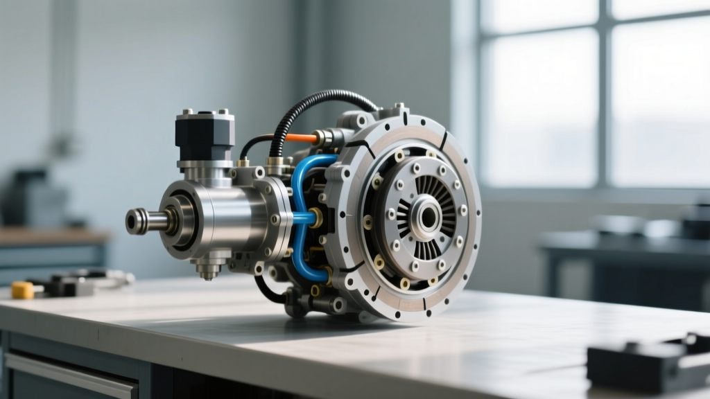
Before interpreting wear signs, technicians must understand the mechanical path from the cab to the bellhousing. The Kenworth clutch pedal assembly typically utilizes a hydraulic-assist system rather than a purely mechanical rod linkage. This system features a master cylinder mounted to the firewall or pedal box, connected via high-pressure hydraulic lines to a slave cylinder or clutch actuator mounted on the transmission bellhousing.
Hydraulic Assist vs. Mechanical Linkage
Modern heavy-duty setups often employ Williams Controls clutch valves or ConMet hydro-assist systems. These systems use air pressure to assist the hydraulic fluid, drastically reducing the physical effort required to depress a 15.5-inch twin-plate clutch. However, this introduces multiple failure points. A spongy pedal feel is rarely indicative of clutch disc wear; instead, it points to air ingress in the hydraulic lines, a failing master cylinder cup, or a worn slave cylinder pushrod. True clutch wear manifests differently, primarily through changes in pedal travel geometry and engagement points.
Primary Wear Signs Transmitted Through the Pedal
Diagnosing a heavy-duty clutch requires reading the physical feedback of the pedal. Technicians should monitor three critical indicators that signal the end of a clutch pack's service life.
1. Diminishing Pedal Free Play
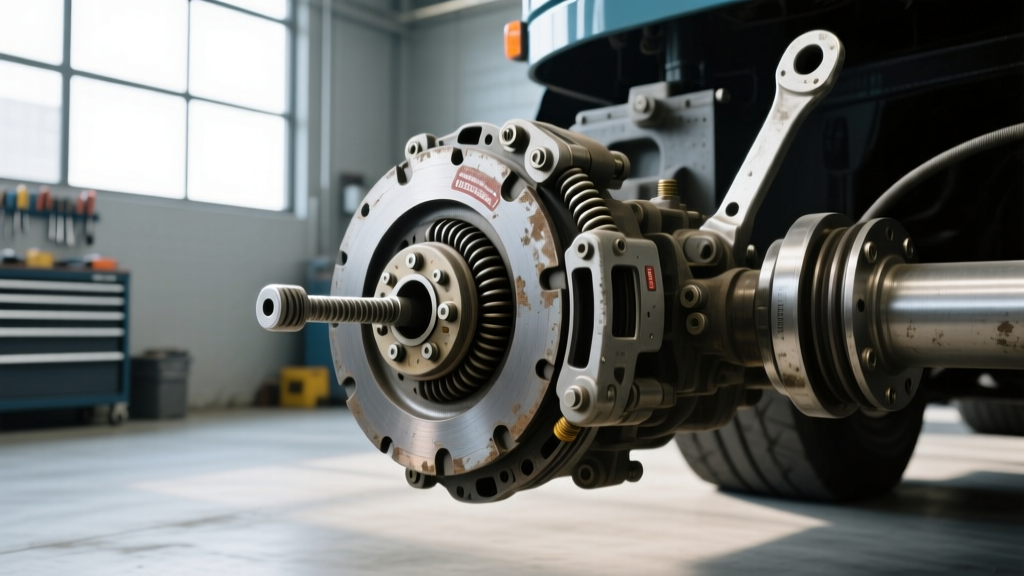
Pedal free play is the distance the pedal travels before the release bearing (throw-out bearing) makes contact with the diaphragm spring fingers of the pressure plate. For most Kenworth trucks equipped with Eaton Solo or Solo Advantage clutches, the specified free play at the pedal pad is between 1.5 inches and 2.0 inches. As the friction discs wear down, the pressure plate moves closer to the flywheel. This causes the diaphragm spring fingers to pivot outward toward the release bearing, effectively reducing the clearance. If the Kenworth clutch pedal free play drops below 1 inch, the release bearing will ride constantly against the spinning spring fingers. This generates immense heat, leading to premature bearing failure and eventual scoring of the transmission input shaft bearing retainer collar.
2. The Clutch Brake Squeeze Failure
Heavy-duty manual transmissions utilize a clutch brake—a small friction disc located at the base of the clutch assembly designed to stop the transmission input shaft from spinning when the vehicle is stationary. This allows the driver to engage first or reverse gear without grinding. The 'clutch brake squeeze' is measured as the distance between the fully depressed pedal and the floor mat. The industry standard for proper engagement is 0.500 inches to 0.750 inches (1/2 to 3/4 inch) from the floor. If the friction discs are severely worn, the release bearing travels too far forward, and the pedal bottoms out against the floor before the clutch brake is fully compressed. If a driver reports difficulty engaging stationary gears or hears grinding when shifting into reverse, and the pedal squeeze measures less than 1/2 inch, the clutch pack is worn beyond its service limit.
3. Torsional Vibration and Pedal Chatter
Heavy-duty clutch discs are equipped with internal dampener springs designed to absorb the violent torsional vibrations produced by high-torque diesel engines like the Cummins X15 or PACCAR MX-13. When these dampener springs fatigue, fracture, or lose their tension, low-frequency vibrations bypass the drivetrain and travel directly up the clutch fork and linkage into the cab. This manifests as a distinct chatter or buzzing sensation in the Kenworth clutch pedal during initial engagement, particularly under heavy load or on inclines. This is a definitive mechanical failure of the disc dampeners, necessitating immediate transmission removal.
Quantifying Clutch Lifespan: Duty Cycles and Indicators
Clutch lifespan in Class 8 vehicles is rarely dictated by mileage alone; it is a function of operational duty cycles, gross combination weight (GCW), and driver habits. The table below outlines expected lifespan indicators based on vocational profiles.
| Duty Cycle Profile | Average GCW | Expected Lifespan (Miles) | Primary Wear Factor |
|---|---|---|---|
| Long-Haul OTR (Highway) | 80,000 lbs | 500,000 - 750,000 | Friction material degradation |
| Regional / LTL Freight | 65,000 lbs | 300,000 - 450,000 | Thermal cycling from frequent stops |
| Heavy-Haul / Vocational | 105,000+ lbs | 150,000 - 250,000 | High-torque slip and dampener fatigue |
'In heavy-haul operations, we do not measure clutch life in miles; we measure it in torque events. A single severe slip event pulling 140,000 lbs up a 6% grade can glaze a twin-plate ceramic disc, effectively ending its lifespan regardless of the odometer reading.' — Senior Fleet Maintenance Director, 2026 Heavy-Duty Drivetrain Symposium.
Precision Diagnostic Procedures and Torque Specifications
When pedal diagnostics confirm the need for a teardown, precision during reassembly is non-negotiable. Heavy-duty drivetrains operate under extreme tolerances. Below are critical specifications for technicians servicing Kenworth trucks with Cummins X15 powertrains and Eaton Solo Advantage 15.5-inch 2-Plate clutches.
- Pedal Free Play Adjustment: Adjust the slave cylinder pushrod or mechanical linkage to achieve exactly 1.5 inches of free play at the center of the pedal pad.
- Clutch Brake Squeeze Verification: Ensure 0.500' to 0.625' of travel remains at the bottom of the pedal stroke to fully engage the clutch brake.
- Flywheel to Crankshaft Torque: Cummins X15 flywheel mounting bolts must be torqued to 165 lb-ft (224 Nm) using a calibrated star-pattern sequence to prevent flywheel runout, which causes pedal pulsation.
- Pressure Plate Cap Screws: Eaton Solo Advantage pressure plate bolts require 35 to 45 lb-ft of torque. Over-torquing will distort the clutch cover, leading to uneven release and severe pedal vibration.
- Pilot Bearing Clearance: Always replace the pilot bearing. Input shaft to pilot bearing clearance must not exceed 0.005 inches. Excessive play will cause the input shaft to wobble, destroying the release bearing and causing a erratic pedal feel.
Economic Analysis: Rebuild vs. Replace in 2026
The decision to replace a heavy-duty clutch involves significant capital expenditure. As of 2026, a premium OEM replacement kit, such as the Eaton Solo Advantage 2-Plate ceramic assembly, ranges from $1,400 to $1,900 depending on the specific torque rating (e.g., 1,850 lb-ft vs 2,050 lb-ft models). When factoring in a heavy-duty clutch brake ($120), a new release bearing and fork assembly ($350), and machine shop flywheel surfacing ($250), parts alone approach $2,500.
Labor is the most substantial variable. Dropping a heavy-duty transmission requires specialized shop equipment and typically bills between 10 to 14 hours. At an average heavy-duty shop rate of $165 per hour, labor costs range from $1,650 to $2,310. Consequently, a comprehensive Kenworth clutch replacement routinely totals between $4,150 and $4,810. Because the labor cost to remove the transmission is so high, technicians must never reuse the clutch fork pivot ball, the slave cylinder, or the hydraulic master cylinder if they show any signs of wear. Replacing these peripheral components during the initial service prevents a $2,000 labor charge for a $40 master cylinder failure 50,000 miles down the road.
Authoritative References
For official service manuals, torque sequences, and diagnostic flowcharts, technicians should consult Eaton Vehicle Clutches for Solo and Advantage series specifications. For powertrain mating tolerances and flywheel runout limits, refer to Cummins Components and OEM service portals. Additional industry trends and vocational maintenance strategies can be reviewed via Fleet Owner Magazine.