Technical Deep-Dive: John Deere 757 PTO Clutch Wear & Lifespan Diagnostics
For commercial landscaping fleets operating in 2026, maximizing equipment uptime is a matter of strict margin control. The John Deere 757 zero-turn mower, typically equipped with the robust 25 HP Kawasaki FD731V engine, relies on an electromagnetic Power Take-Off (PTO) clutch to engage and disengage the mower deck blades. Unlike manual automotive friction clutches, the john deere 757 pto clutch operates via a stationary electromagnetic coil that pulls a rotating armature against a friction disc. Over hundreds of operational hours, this system endures extreme thermal cycling, shock loads from blade engagement, and environmental contamination.
Understanding the precise wear signs, electrical degradation markers, and mechanical lifespan indicators of this specific PTO assembly is critical for fleet managers and small engine technicians. This guide provides a comprehensive diagnostic framework for evaluating PTO clutch health, complete with OEM specifications, adjustment procedures, and replacement economics.
Anatomy of the JD 757 Electromagnetic PTO Clutch
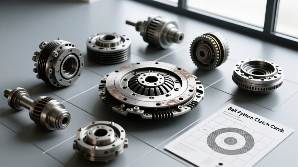
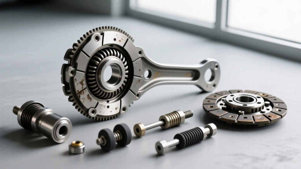
The John Deere 757 utilizes a heavy-duty electromagnetic friction clutch, commonly manufactured by industry leaders like Warner Electric (e.g., Warner 5319-45 equivalent) or Ogura (GT2.5 series). To accurately diagnose wear, you must understand the three primary wear interfaces:
- The Electromagnetic Coil (Rotor): A copper-wound coil housed in a steel shell. It does not rotate and is responsible for generating the magnetic flux when 12V DC is applied.
- The Armature: A solid steel plate that rotates with the crankshaft. When energized, the magnetic field pulls the armature across the air gap.
- The Friction Disc & Rotor Assembly: The rotating output side connected to the mower deck belt. The armature clamps against the friction material to transfer engine torque to the blades.
Expert Insight: PTO clutch failure on the JD 757 is rarely a sudden catastrophic event. It is almost always preceded by micro-slippage, which generates excessive heat, accelerates friction material degradation, and eventually burns out the internal coil insulation due to thermal soak-back.
Primary Mechanical Wear Signs
1. Air Gap Widening and Engagement Slippage
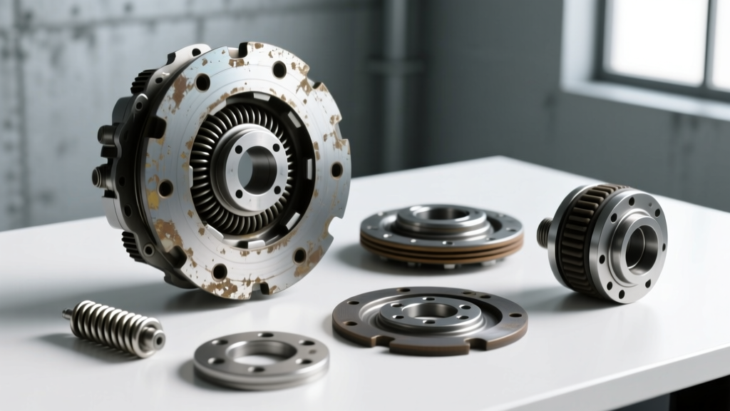
As the friction material on the rotor assembly wears down, the physical distance between the armature and the rotor (the air gap) increases. Magnetic flux density drops exponentially as the gap widens. If the gap exceeds 0.020 inches, the 12-volt electromagnet often lacks the pulling force to achieve full clamping pressure. This results in micro-slippage during heavy cutting operations (e.g., tall, wet grass). Slippage generates surface temperatures exceeding 400°F (204°C), leading to glazed friction surfaces and eventual thermal failure.
2. Armature Drag and Residual Magnetism
A common wear indicator on high-hour JD 757 mowers is 'armature drag.' When the PTO switch is turned off, the mower deck blades should stop relatively quickly. If the blades continue to spin for an extended period, or if you hear a metallic scraping noise post-disengagement, the armature is dragging against the rotor. This is caused by either residual magnetism in the coil housing, warped friction surfaces due to thermal warping, or a failing internal return spring mechanism.
3. Bearing Degradation
The PTO clutch houses a sealed double-row ball bearing that supports the rotating assembly. Bearing wear is usually the first audible sign of clutch degradation. A high-pitched whining or squealing noise that changes pitch with engine RPM—before the PTO is even engaged—indicates bearing race pitting or grease starvation. If left unaddressed, bearing failure will cause the clutch to wobble, destroying the crankshaft seal and potentially snapping the Kawasaki engine's crankshaft.
Electrical Diagnostics: Coil & Circuit Health
Before condemning a slipping PTO clutch to the scrap bin, you must rule out electrical starvation. A weak magnetic field mimics mechanical wear perfectly.
Voltage Drop Testing
Do not test the battery; test the clutch pigtail. Set your multimeter to DC Voltage. Back-probe the PTO clutch connector while the mower is running at 3600 RPM and the PTO is engaged. You must read a minimum of 12.5V DC at the clutch terminals. If you read 10.5V or lower, the clutch is starving for current due to a failing PTO switch, corroded harness grounds, or a weak stator/alternator. Operating a PTO clutch below 11.5V guarantees premature friction wear.
Coil Resistance (Ohm) Testing
Disconnect the clutch and set your multimeter to Ohms (Ω). Measure across the two pins on the clutch coil. The resistance of a healthy JD 757 PTO clutch coil should fall within a very specific window, heavily dependent on ambient temperature.
| Ambient Temperature | Target Coil Resistance (Ohms) | Diagnostic Verdict if Out of Spec |
|---|---|---|
| 50°F (10°C) | 2.4 Ω - 2.8 Ω | Internal short (if lower) or open circuit (if infinite) |
| 70°F (21°C) | 2.8 Ω - 3.3 Ω | Optimal operating specification |
| 100°F (38°C) | 3.3 Ω - 3.9 Ω | Thermal degradation of copper windings (if significantly higher) |
Reference data based on standard 12V commercial electromagnetic clutch windings. For exact OEM tolerances, consult Warner Electric technical bulletins or Ogura Industrial PTO specifications.
Precision Air Gap Adjustment Procedure
If your electrical tests pass but the clutch slips under load, the friction material has likely worn, requiring an air gap adjustment. This is a mandatory lifespan-extending maintenance procedure.
- Clean the Interface: Use compressed air and electrical contact cleaner to remove grass clippings and oil from the armature and rotor faces.
- Measure the Gap: Insert a feeler gauge through the three adjustment slots on the clutch assembly. Measure the distance between the armature and the rotor face.
- Evaluate: If the gap exceeds 0.018 inches, adjustment is required. The target specification is 0.012 to 0.015 inches.
- Adjust: Loosen the three adjustment nuts (typically 3/8" or 10mm). Turn the nuts clockwise to draw the armature closer to the rotor. Check all three slots to ensure the gap is perfectly uniform. An uneven gap will cause the armature to bind and chatter upon engagement.
- Secure: Tighten the adjustment nuts to 12-15 ft-lbs. Apply a drop of blue Loctite 243 to the threads to prevent vibration-induced backing out.
Lifespan Indicators: When to Rebuild vs. Replace
How long should a john deere 757 pto clutch last? In commercial fleet environments, a well-maintained PTO clutch will yield between 900 and 1,400 operational hours. However, lifespan is dictated by engagement habits and maintenance intervals.
The Burn-In Procedure (Crucial for New Installs)
When replacing the clutch, technicians often skip the burn-in procedure, leading to failure within the first 50 hours. New friction surfaces have microscopic machining peaks. To seat the friction material properly:
- Engage the PTO at half-throttle (approx. 1800 RPM).
- Allow the blades to reach full speed, then disengage.
- Repeat this cycle 10 to 15 times with a 30-second cooling interval between cycles.
- This process heat-cycles the friction material, burnishing it to the armature face and preventing immediate glazing during heavy field use.
Economic Breakdown: OEM vs. Aftermarket (2026 Pricing)
When the coil reads open, the bearing is seized, or the friction material is worn past the adjustment limit, replacement is mandatory. Fleet managers must weigh OEM dealer costs against premium aftermarket alternatives.
| Component Source | Estimated Cost (2026) | Warranty & Lifespan Expectancy |
|---|---|---|
| OEM John Deere (Dealer) | $380 - $460 | 6-Month / 1,200 Hours |
| Premium Aftermarket (Xtreme / Warner) | $190 - $250 | 1-Year / 1,000+ Hours |
| Budget Import (eBay / Amazon) | $80 - $120 | None / 200-400 Hours (Not Recommended) |
For verified OEM part cross-references and maintenance schedules, always refer to the John Deere Parts & Maintenance portal.
Crankshaft Mounting Torque & Installation Warnings
A frequently overlooked cause of premature PTO clutch failure on the Kawasaki FD731V engine is improper mounting torque. The PTO clutch acts as a harmonic damper for the engine's power pulses. If the main crankshaft bolt is under-torqued, the clutch will fret against the crankshaft keyway, elongating the keyway and destroying both the clutch hub and the engine crankshaft.
Installation Specs:
- Bolt Thread Prep: Clean crankshaft threads with a wire brush and brake cleaner. Apply medium-strength threadlocker (Loctite 243).
- Torque Specification: Torque the main PTO mounting bolt to 55 - 65 ft-lbs (Verify thread pitch: M12x1.25 vs 1/2-20 UNF depending on exact engine serial number).
- Anti-Rotation: Use a strap wrench on the clutch housing or engage the parking brake and block the deck blades to prevent engine rotation during torquing. Never pry against the friction disc to hold the assembly.
Summary
Diagnosing the john deere 757 pto clutch requires moving beyond simple visual inspections. By integrating voltage drop testing, precise coil resistance measurements, and strict adherence to air gap tolerances (0.012" - 0.015"), technicians can accurately predict clutch failure before it strands a crew in the field. Recognizing the subtle auditory cues of bearing degradation and the thermal signs of micro-slippage ensures that your commercial mowers maintain peak blade tip speed and operational efficiency throughout the 2026 mowing season and beyond.