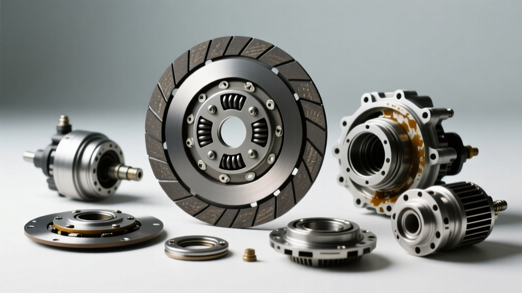
The Challenge of Intermittent Fan Clutch Failures
While AutogearNexus primarily focuses on transmission and drivetrain clutch systems, the term 'clutch' extends to the engine cooling system. In 2026, millions of internal combustion engine (ICE) trucks, SUVs, and commercial vehicles still rely on engine-driven cooling fans. When technicians and DIYers search for guidance on intermittent clutch problems diagnosis, they are frequently dealing with a failing fan clutch rather than a slipping manual transmission disc. A fan clutch that engages unpredictably can lead to severe engine overheating in traffic, excessive parasitic drag on the highway, or a roaring noise that mimics a failing wheel bearing.
Diagnosing an intermittent fan clutch requires understanding the precise mechanics of viscous fluid dynamics and electronic Pulse Width Modulation (PWM) signals. In this comprehensive guide, we will break down exactly how to check fan clutch operation, identify the root causes of intermittent engagement, and provide the specific torque specs and diagnostic frameworks needed to fix the issue permanently.
Understanding Fan Clutch Types: Thermal vs. Electronic
Before grabbing your tools, you must identify which type of clutch is bolted to your water pump shaft. The diagnostic approach varies wildly between the two primary designs found on modern and legacy vehicles.
1. Thermal and Viscous Fan Clutches
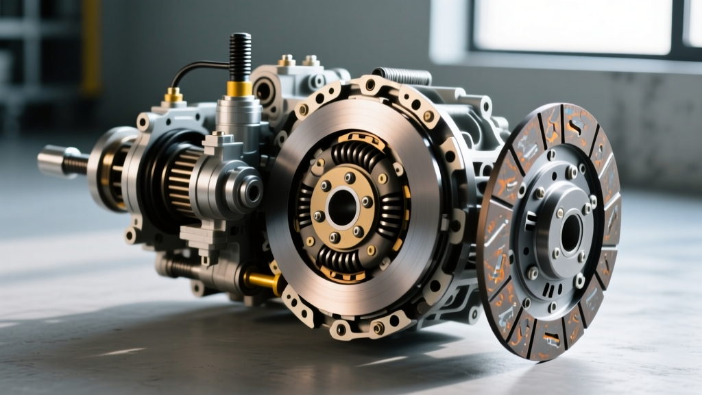
Common on vehicles like the GM Silverado (LS/LT V8 platforms) and older Ford F-150s, thermal fan clutches rely on a high-molecular-weight silicone fluid (polydimethylsiloxane). A bimetallic thermostatic coil spring on the front face of the clutch reacts to the temperature of the air passing through the radiator. When the air hits approximately 195°F to 210°F, the coil expands, opening an internal valve. This allows the viscous fluid to enter the working chamber, locking the fan to the water pump shaft. Intermittent problems here usually stem from fluid degradation, internal valve sludge, or bimetallic spring fatigue.
2. Electronic and ECM-Controlled Fan Clutches
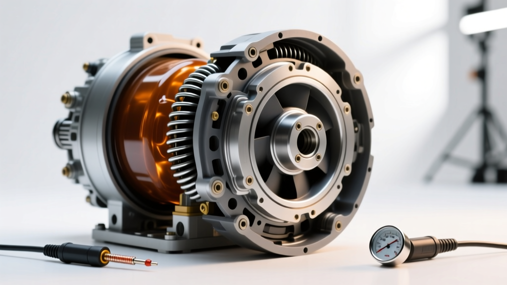
Heavy-duty trucks, such as the RAM Cummins 2500/3500 and Ford Super Duty (6.7L Powerstroke), utilize electronic fan clutches. These do not rely on ambient air temperature. Instead, the Powertrain Control Module (PCM) sends a PWM voltage signal to an electromagnetic coil inside the clutch. The PCM calculates the required fan speed based on coolant temperature, A/C head pressure, and transmission fluid temperature. Intermittent failures in these systems are almost always electrical—typically caused by wiring harness chafing against the radiator shroud or a failing internal solenoid.
Step-by-Step Guide: How to Check Fan Clutch Operation
To accurately perform intermittent clutch problems diagnosis, you must test the system across different thermal states. Follow these professional steps to isolate the failure.
Step 1: The Cold Startup Spin Test (Baseline Resistance)
With the engine completely cold and OFF, attempt to spin the fan blade by hand.
- Normal: You should feel a slight, smooth viscous drag. The fan should not spin freely like a bicycle wheel in neutral, nor should it be completely locked.
- Abnormal: If it spins with zero resistance, the internal fluid has leaked out (check for oily residue around the clutch hub). If it is completely locked and won't budge, the internal valve is seized in the engaged position.
Step 2: The Heat-Soak Engagement Test
This test verifies the thermal activation of the bimetallic spring.
- Start the engine cold and let it idle. The fan should remain relatively quiet.
- Allow the engine to reach normal operating temperature (upper radiator hose should be hot and pressurized, typically 190°F+).
- Use an infrared thermometer to measure the temperature of the radiator core directly behind the fan clutch.
- Once the radiator core exceeds 200°F, briefly rev the engine to 2,000 RPM.
- The Result: You should hear a distinct, aggressive 'roar' as the clutch engages and pulls air. If the clutch engages, then disengages repeatedly while the engine is still hot, you have confirmed an intermittent thermal clutch failure.
Step 3: Electronic Fan Clutch PWM Signal Testing
For ECM-controlled clutches, you need a digital multimeter (DMM) with a duty cycle function or an automotive oscilloscope. Back-probe the PWM signal wire at the clutch connector. With the engine running and the A/C turned to MAX (which forces a high-duty cycle fan command), you should see a PWM signal ranging from 10% (disengaged) to 80%+ (fully locked). If the signal from the PCM is steady at 80%, but the fan clutch intermittently drops out and stops pulling air, the internal electromagnetic coil is failing under heat load.
Diagnosing Intermittent Clutch Problems: Symptom Matrix
Use the following diagnostic table to cross-reference your specific symptoms with the most likely root causes. This framework is essential for efficient intermittent clutch problems diagnosis.
| Intermittent Symptom | Probable Root Cause | Diagnostic Action & Fix |
|---|---|---|
| Fan roars loudly on cold startup, then quiets down after 2 minutes. | Viscous fluid pooling in the working chamber overnight due to gravity. | Normal behavior for many thermal clutches. No repair needed unless it persists past 3 minutes. |
| Fan engages and disengages rapidly (cycling) at highway speeds. | Failing bimetallic coil spring or degraded silicone fluid losing shear strength. | Replace the thermal fan clutch assembly. Do not attempt to rebuild or refill. |
| Engine overheats in stop-and-go traffic, but cools down on the highway. | Internal valve sticking in the disengaged position; clutch slipping under load. | Perform the 'Newspaper Roll Test' at idle. If the fan stops instantly when lightly obstructed, replace the clutch. |
| Random check engine light (e.g., P052E or P0691) with erratic fan speeds. | Chafed PWM wiring harness or corroded pigtail connector at the clutch solenoid. | Inspect the wiring loom near the radiator shroud for vibration wear. Repair wires and apply dielectric grease. |
Removal, Torque Specs, and Replacement Best Practices
Once you have determined how to check fan clutch systems and confirmed a failure, proper removal is critical. The fan clutch is threaded onto the water pump shaft, and the thread direction depends on the engine's rotation and water pump design.
Crucial Thread and Wrench Data
- GM LS/LT V8 Engines: Typically requires a 47mm (or 1 7/8-inch) wrench. Most standard-rotation water pumps use a standard (right-hand) thread. You must use a serpentine belt holding tool to prevent the pulley from spinning while you break the nut loose.
- Cummins 5.9L / 6.7L (Dodge/RAM): Requires a 36mm wrench. These are often reverse (left-hand) threaded. Remember: turn clockwise to loosen.
- Ford 6.7L Powerstroke: Electronic clutches often require a 36mm or 47mm wrench depending on the exact year, and extreme care must be taken not to damage the fragile PWM pigtail during removal.
Torque Specifications
While you should always consult the OEM service manual for your specific 2026 vehicle application, general torque specifications for fan clutch retaining nuts to the water pump shaft range between 35 lb-ft and 45 lb-ft. Over-torquing can crack the internal valve body of a thermal clutch or damage the electromagnetic coil housing on an electronic unit. Always apply a mild thread locker (like Loctite Blue 242) if specified by the manufacturer, especially on reverse-threaded applications prone to vibration-induced backing out.
Drivetrain vs. Cooling System: Don't Cross the Wires
As automotive technology evolves in 2026, the line between mechanical and electronic systems continues to blur. While a slipping clutch pedal or a shuddering torque converter in a ZF 8HP transmission requires entirely different diagnostic protocols (such as checking hydraulic line pressure or clutch pack clearance), the fundamental concept of 'intermittent engagement' remains the same across all clutch systems. Whether you are diagnosing a PWM-controlled transmission lock-up clutch or an electronic engine fan clutch, relying on data logs, oscilloscope readings, and precise thermal testing will always yield better results than guesswork.
For further reading on advanced thermal management systems and electronic cooling diagnostics, refer to the SAE International Technical Papers database. Additionally, the AA1Car Automotive Library provides excellent baseline schematics for legacy thermal clutch systems, while Auto Service Professional regularly publishes updates on OEM technical service bulletins (TSBs) related to electronic fan clutch wiring harness recalls.
By methodically applying these tests, you can confidently solve intermittent clutch problems diagnosis, restore your vehicle's cooling efficiency, and prevent catastrophic engine overheating.