Decoding the Hydraulic Clutch Pedal Diagram for Preventive Diagnostics
When diagnosing manual transmission engagement issues, the hydraulic clutch pedal diagram is your foundational roadmap. Unlike older mechanical linkage systems that relied on cables and Z-bars, modern hydraulic circuits utilize Pascal’s Law to multiply pedal force and actuate the release bearing. As we navigate the 2026 automotive landscape, where high-torque manual platforms like the Tremec T56 Magnum-F and Ford MT-82 are pushed to their limits, understanding the schematic of your hydraulic circuit is no longer optional—it is a critical preventive maintenance skill.
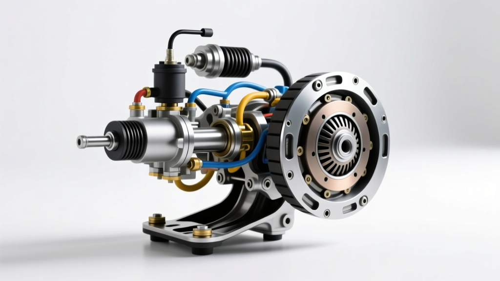
A standard hydraulic clutch pedal diagram maps the journey of hydraulic pressure from the driver’s foot to the clutch fork or concentric slave cylinder (CSC). By tracing this diagram, technicians can isolate failure points, calculate hydraulic volume deficits, and prevent catastrophic drivetrain damage before a minor seal leak turns into a stranded vehicle.
Core Components Mapped on the Hydraulic Schematic
Before performing any preventive maintenance, you must identify the primary nodes on your specific clutch pedal diagram. While layouts vary between OEM manufacturers, the fundamental architecture remains consistent.
1. The Master Cylinder and Pushrod Assembly
Located at the firewall, the master cylinder converts mechanical pedal travel into hydraulic pressure. The diagram will highlight the compensation port, a tiny orifice that connects the reservoir to the high-pressure bore. When the pedal is fully released, this port allows fluid to return to the reservoir, accommodating thermal expansion. If this port becomes blocked by degraded rubber seals or contaminated fluid, the clutch will drag, leading to premature synchro wear and gear grind.
2. Hydraulic Hardlines and Flex Hoses
The schematic routes fluid through steel-braided or OE rubber flex hoses. Rubber hoses are notorious for internal delamination over time. A collapsed inner liner acts as a one-way check valve, allowing fluid to the slave cylinder but restricting its return, resulting in a clutch that fails to fully re-engage.
3. Slave Cylinder Configurations
Your diagram will dictate whether your system uses an external slave cylinder (pushing a traditional clutch fork) or a Concentric Slave Cylinder (CSC) that wraps around the transmission input shaft. CSCs, common in modern bellhousings, eliminate the pivot ball and fork geometry but require transmission removal for preventive replacement.
Pedal Ratio and Hydraulic Volume Calculations
True E-E-A-T in clutch diagnostics requires understanding the math behind the diagram. Pedal ratio and cylinder bore sizes dictate the system's hydraulic volume and mechanical advantage.
Engineering Insight: If your pedal ratio is 6:1 and you apply 100 lbs of foot pressure, the master pushrod receives 600 lbs of force. If the master cylinder bore is 0.750-inch (Area = 0.441 sq in), system pressure reaches roughly 1,360 PSI. If the slave cylinder bore is 0.875-inch (Area = 0.601 sq in), the slave exerts 817 lbs of force on the pressure plate fingers. Altering bore sizes during aftermarket upgrades fundamentally shifts this balance, often causing bottoming-out or incomplete disengagement.
Fluid Specifications and Preventive Flushing Protocols
Hydraulic clutch systems share the same glycol-ether based fluids as brake systems. Because these fluids are highly hygroscopic (water-absorbing), moisture ingress lowers the boiling point and promotes internal corrosion in the master and slave cylinders. According to SAE International standards, adhering to the correct fluid specification is paramount for seal longevity.
| Fluid Type | Dry Boiling Point | Wet Boiling Point (3.7% Water) | Preventive Flush Interval |
|---|---|---|---|
| DOT 3 | 401°F (205°C) | 284°F (140°C) | Every 24 Months / 30k Miles |
| DOT 4 | 446°F (230°C) | 311°F (155°C) | Every 36 Months / 45k Miles |
| DOT 5.1 | 518°F (270°C) | 374°F (190°C) | Every 48 Months / 60k Miles |
| DOT 5 (Silicone) | 500°F (260°C) | Does Not Absorb Water | NEVER USE IN CLUTCH SYSTEMS |
Critical Warning: Never use DOT 5 silicone fluid in a standard clutch hydraulic circuit. Its high compressibility results in a spongy pedal feel, and it will rapidly degrade standard EPDM rubber seals designed for glycol-based fluids.
Diagnosing Common Hydraulic Failures Using the Diagram
By referencing your clutch pedal diagram, you can systematically isolate the following common failure modes without immediately dropping the transmission.
Symptom: The Spongy or Soft Pedal
Diagnosis: Air ingress or fluid boiling. Air is compressible; fluid is not. Check the diagram's high-points, particularly the master cylinder output port and the slave cylinder bleeder screw orientation. If the bleeder screw is not at the absolute highest point of the slave cylinder housing (a common flaw in some aftermarket CSCs), an air pocket will become trapped, requiring a reverse-bleeding pressure tool to evacuate.
Symptom: Pedal Creeping to the Floor
Diagnosis: Master cylinder internal bypass. If the pedal slowly sinks to the floor while held down at a stoplight, the primary cup seal inside the master cylinder is allowing fluid to bypass from the high-pressure side back into the reservoir. There are no external leaks. Replacement of the master cylinder is required.
Symptom: Incomplete Disengagement (Gear Crunch)
Diagnosis: Slave cylinder travel deficit or flex hose expansion. Measure slave pushrod travel. A standard external slave should yield between 0.450" and 0.550" of travel. If travel is insufficient, the old rubber flex hose may be ballooning under pressure, absorbing hydraulic volume. Upgrading to a stainless-steel braided line resolves this volume loss.
Real-World Applications: T56 Magnum and MT-82 Systems
Let us apply this diagnostic framework to two of the most prevalent manual platforms on the road today, referencing data aligned with Tremec's official technical documentation and OE service guidelines.
GM LS / Tremec T56 Magnum (External Slave)
- Configuration: External slave cylinder actuating a stamped steel fork.
- OEM Part Reference: Sachs SH5021 (or GM #19299480).
- Preventive Cost: $85 - $130 for the slave cylinder.
- Torque Spec: Slave cylinder mounting nuts must be torqued to 25 Nm (18 lb-ft). Over-torquing can warp the cylinder bore, causing premature piston seal failure.
- Diagram Note: The T56 external system requires a specific 10mm bleeder wrench. Ensure the quick-connect fitting at the firewall is fully seated; a partially clipped line will leak fluid only under high-pressure actuation.
Ford Mustang MT-82 (Concentric Slave Cylinder)
- Configuration: Internal CSC wrapping the input shaft.
- OEM Part Reference: Exedy / Ford OEM CSC assembly.
- Preventive Cost: $160 - $240 (requires transmission removal).
- Diagram Note: The MT-82 diagram features a complex thermal shield and a specific fluid routing tube. When performing preventive maintenance, the CSC must be bench-bled using a specialized vacuum tool before installation to ensure no air is trapped inside the bellhousing.
Step-by-Step Preventive Maintenance Checklist
To maintain optimal hydraulic health and prevent premature clutch wear, integrate the following protocol into your vehicle's service schedule:
- Visual Fluid Inspection (Every Oil Change): Check the reservoir. Fluid should be clear to light amber. If it is dark brown or black, the rubber seals are degrading, and a flush is immediately required.
- Pushrod Free-Play Measurement (Annually): Measure the free-play at the master cylinder pushrod. There should be 1mm to 2mm of free-play before the piston engages. Zero free-play keeps the compensation port partially blocked, leading to clutch drag and overheating.
- Pressure Bleeding (Every 40,000 Miles): Avoid manual 'pump-and-hold' bleeding, which can cause the master cylinder piston to over-travel and score the bore. Use a pressure bleeder (e.g., Motive Products 0107) set to 10-15 PSI to push fresh fluid through the system safely.
- Flex Hose Inspection (Every 60,000 Miles): Inspect the rubber flex hose for micro-cracking, bulging, or chafing against the chassis. Replace proactively with a braided stainless line to improve pedal firmness and hydraulic consistency.
Conclusion
The hydraulic clutch pedal diagram is more than a schematic; it is a diagnostic flowchart. By understanding the relationship between bore sizes, fluid dynamics, and component layout, you can transition from reactive repairs to proactive preventive maintenance. Whether you are maintaining a daily-driven commuter or a high-horsepower track car, respecting the hydraulic circuit ensures crisp shifts, prolonged synchro life, and ultimate drivetrain reliability.