Diagnostic Framework for Auxiliary Cooling Failures
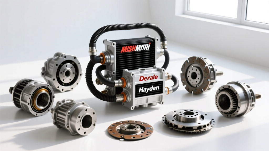
As of 2026, the thermal management of modern automatic transmissions has never been more critical. Whether you are towing heavy loads with a GM 6L80 or managing the precise operating temperatures of a ZF 8HP, an auxiliary cooler is often mandatory. However, the physical connections and core designs vary wildly between manufacturers. When diagnosing a hose transmission cooler circuit, understanding the specific failure modes of the top three brands—Mishimoto, Derale, and Hayden—is essential for accurate troubleshooting.
Transmission fluid leaks, pressure drops, and thermal inefficiencies rarely occur at random. They are usually the result of mismatched fittings, degraded hose materials incompatible with modern low-viscosity synthetics (like Dexron VI or Mercon LV), or improper installation torque. Below, we break down the exact diagnostic procedures for the industry's leading cooler brands.
Mishimoto: Stacked-Plate & AN Fitting Diagnostics
Mishimoto dominates the performance and heavy-duty truck market with its X-Trac and Heavy Duty stacked-plate coolers (e.g., part number MMTC-U or MMTC-F2D). These units utilize aluminum AN fittings, typically -6AN or -8AN, paired with braided stainless steel or PTFE-lined rubber hoses.
Common Failure Modes
- NPT Thread Contamination: Mishimoto coolers often feature NPT (National Pipe Taper) ports that require an adapter to step up to AN flare fittings. A frequent installation error is using standard PTFE thread tape. Under high-flow conditions, tape shreds, enters the cooler core, and blocks the micro-fins, causing a massive pressure drop and subsequent overheating.
- AN Flare Leaks: Unlike NPT threads, 37-degree AN JIC flares seal via metal-to-metal contact. If an aluminum -8AN fitting is over-torqued, the flare will gall or crack, resulting in a slow weep that only manifests when the fluid reaches operating temperature (180°F+) and viscosity drops.
Troubleshooting Protocol
If you suspect a flow restriction or leak in a Mishimoto setup, isolate the cooler lines. Use a digital torque wrench to verify the AN fittings. The correct torque spec for aluminum -8AN fittings is 20 to 25 ft-lbs. If a leak persists at the NPT adapter joint, disassemble it, clean the threads with brake cleaner, and reseal using a liquid PTFE thread sealant (such as Loctite 592) rather than tape. Monitor the Transmission Fluid Temperature (TFT) PID via an OBD2 scanner like FORScan; if temps remain high despite adequate fluid levels, the core is likely obstructed by sealant debris.
Derale: Plate-and-Fin & Barb Fitting Diagnostics
Derale’s Series 8000 (Plate-and-Fin) and Series 9000 (Tube-and-Fin) coolers, such as the popular part number 13503, are the go-to choice for budget-friendly, high-volume cooling. These units rely on 1/2-inch or 3/8-inch barbed aluminum nipples and standard rubber transmission hoses secured by hose clamps.
Common Failure Modes
- High-PSI Hose Blow-Off: Modern transmissions generate immense line pressure. The GM 6L80, for instance, can spike to 275 PSI in reverse or during heavy tow-haul downshifts. Standard worm-gear hose clamps cannot distribute pressure evenly across the rubber hose, leading to micro-tears and catastrophic blow-offs at the barb.
- Rubber Degradation: Older Derale kits included standard nitrile rubber hoses. When exposed to modern synthetic fluids and sustained 220°F+ temperatures, the inner lining can blister, flake off, and clog the transmission's internal valve body solenoids.
Troubleshooting Protocol
Inspect the hose ends at the Derale barbs. If you see fluid weeping or the hose feels spongy, the clamp has failed. Never reuse a worm-gear clamp on a high-pressure transmission circuit. The correct repair is to cut the hose end off, inspect the barb for aluminum scoring, and reinstall using constant-tension T-bolt clamps rated for a minimum of 300 PSI. For a permanent fix, upgrade the rubber lines to PTFE-lined stainless braided hoses with reusable AN-to-barb push-lock fittings. According to the Derale Installation Guides, ensuring at least 1.5 inches of hose seating on the barb is critical to prevent suction-side cavitation.
Hayden Automotive: Rapid-Cool & Quick-Connect Diagnostics
Hayden’s Rapid-Cool (e.g., part number 678) and Ultra-Cool lines are engineered for OEM-style replacements and light-duty auxiliary setups. They frequently utilize plastic or metal quick-connect fittings designed to snap directly into factory transmission lines.
Common Failure Modes
- Quick-Connect Tab Fatigue: The plastic retaining tabs on Hayden’s quick-connect adapters become brittle after years of under-hood heat cycling. A slight tug during a fluid change or engine movement can snap the tab, causing the line to eject under pressure.
- Internal O-Ring Flattening: Inside the quick-connect housing sits a small Viton or EPDM O-ring. Over 60,000 miles, this O-ring flattens out, losing its radial seal. This results in a leak that only appears when the engine is running and line pressure exceeds 40 PSI.
Troubleshooting Protocol
Diagnosing a Hayden quick-connect leak requires a visual inspection with a UV dye added to the transmission fluid. If the leak originates from the collar of the quick-connect, do not attempt to tighten it—these are not threaded. You must depress the internal release collar, remove the fitting, and replace the internal O-ring using a dedicated transmission line O-ring kit. As noted by the Hayden Auto Tech Center, always lubricate the new O-ring with fresh ATF before reassembly to prevent rolling or pinching during insertion.
Comparative Failure & Repair Matrix
| Brand / Series | Core Design | Fitting Style | Primary Failure Point | Diagnostic Repair Spec |
|---|---|---|---|---|
| Mishimoto MMTC | Stacked-Plate | NPT to -8AN Flare | PTFE tape obstruction / Flare galling | Torque 20-25 ft-lbs; Use liquid PTFE |
| Derale 8000/9000 | Plate / Tube-Fin | Aluminum Barb | Hose blow-off under high reverse PSI | Upgrade to T-Bolt clamps (300+ PSI) |
| Hayden Rapid-Cool | Multi-Pass Tube | Quick-Connect | Plastic tab snap / O-ring flattening | Replace internal Viton O-rings |
Advanced Pressure Testing the Cooler Circuit
When visual diagnosis fails, you must perform a static pressure test on the hose transmission cooler loop. Disconnect the cooler return line at the transmission pan and attach a Mityvac 0-300 PSI fluid pressure gauge.
- Start the engine and cycle the transmission through Park, Reverse, Neutral, and Drive (with brakes firmly applied).
- Observe the gauge. A healthy auxiliary cooler circuit should show a pressure drop of less than 5 PSI compared to the main line pressure.
- If the pressure spikes erratically or fails to return to baseline when shifted to Park, you have a restriction in the cooler core or a kinked hose.
- For ZF 8HP applications, remember that the factory thermostat bypasses the cooler until the fluid reaches roughly 185°F. You must use a bi-directional scanner to command the thermostat open before testing the external cooler circuit flow.
Expert Insight: Never use compressed air to blow out a suspected clog in a stacked-plate cooler. The internal brazed joints are not designed for high-pressure air, and you risk rupturing the core internally, which will introduce moisture into your ATF. Always flush using a dedicated transmission flush machine or low-pressure solvent.
By understanding the distinct engineering choices of Mishimoto, Derale, and Hayden, technicians and DIYers can move beyond guesswork. Properly matching your hose materials, clamp types, and fitting torques to the specific cooler brand ensures your transmission survives the extreme thermal demands of modern towing and performance driving.