The 6L80 Internal Mode Switch: Beyond Standard Transmission Speed Sensor Repair
When diagnosing late-model GM vehicles equipped with the ubiquitous 6L80 and 6L90 transmissions, technicians frequently encounter shift-related diagnostic trouble codes (DTCs). While a standard transmission speed sensor repair typically addresses issues like torque converter clutch shudder, erratic shift points, or speedometer dropouts caused by failing input/output (ISS/OSS) magnetic pickups, an entirely different beast lurks within the Transmission Control Module's (TCM) logic: the Transmission Range Sensor (TRS).
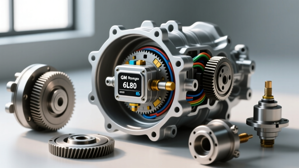
On the GM 6L80 platform, this component is officially designated as the Internal Mode Switch (IMS). Despite the word 'internal' in its name, the IMS is actually mounted externally on the side of the transmission case, actuated by the manual shaft. This design quirk means that unlike a speed sensor repair—which mandates dropping the transmission pan, draining 10+ quarts of Dexron VI fluid, and fishing metallic debris out of the valve body—the IMS can often be serviced without losing a single drop of fluid, provided the manual shaft seal remains intact.
In this 2026 model-specific repair guide, we will bypass the generic advice and dive deep into the exact diagnostic procedures, binary logic decoding, and mechanical alignment steps required to successfully replace the 6L80 IMS.
Decoding the 4-Bit Binary Logic of the 6L80 IMS
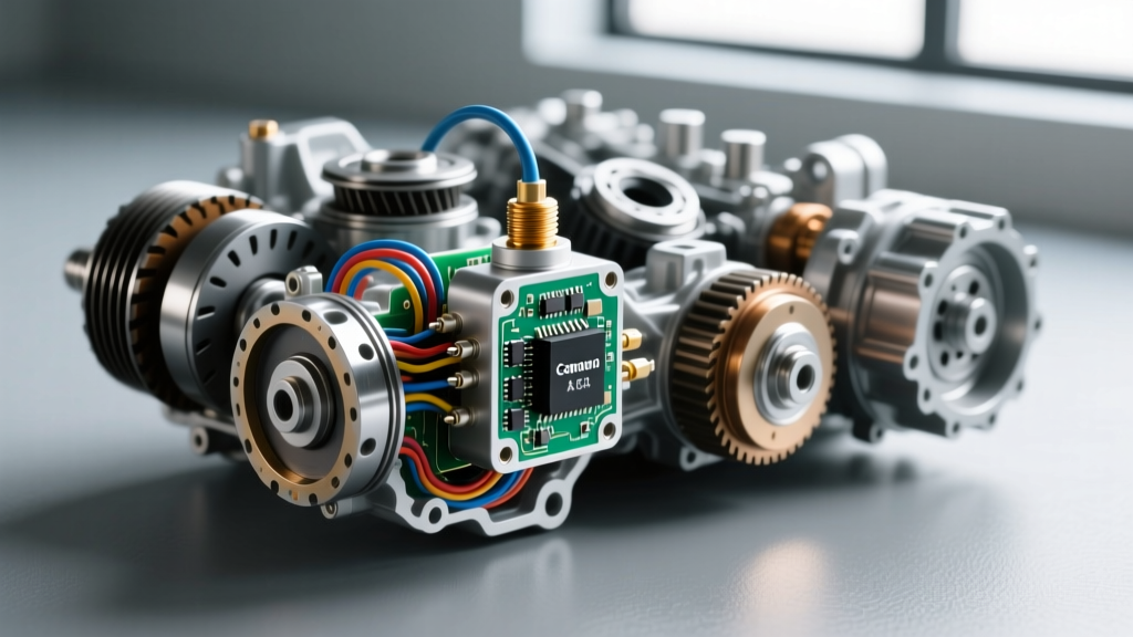
To properly diagnose transmission range sensor problems, you must understand how the TCM interprets gear selection. The 6L80 IMS does not use a simple variable resistor or rheostat like older Ford or Chrysler units. Instead, it utilizes a 4-bit binary switch matrix consisting of Signal A, Signal B, Signal C, and a Parity (P) signal.
As the driver moves the shift lever, the manual shaft rotates a wiper ring inside the IMS, opening and closing contacts to ground. The TCM reads these four signals simultaneously. The Parity bit acts as a checksum; if the TCM reads a combination of signals that does not match the factory programmed truth table (for example, if it sees the binary code for both 'Park' and 'Reverse' simultaneously due to worn internal contacts), it immediately flags a circuit malfunction.
Common DTCs Associated with TRS Failure
- P0705 (Transmission Range Sensor Circuit Malfunction): The TCM detects an invalid binary combination or a parity error. This is the most common code for a failing 6L80 IMS.
- P0706 (Transmission Range Sensor Circuit Range/Performance): The sensor signal is technically valid but falls outside the expected parameters, often caused by a misaligned sensor during a previous repair or a bent manual linkage.
- P0708 (Transmission Range Sensor Circuit High Input): An open circuit condition, usually indicating a broken wire in the harness leading from the TCM to the IMS connector, or severe internal corrosion on the sensor pins.
Multimeter Pinout Testing and Diagnostics
Before condemning the sensor and ordering parts from ACDelco's transmission management catalog, verify the harness integrity. The IMS connector typically features a 6-pin layout (Power, Ground, Signal A, Signal B, Signal C, Parity).
- Disconnect the IMS electrical connector and inspect for Dexron VI fluid intrusion. Capillary action can wick fluid past a failing internal seal, destroying the circuit board.
- Set your multimeter to DC Volts. With the key on, engine off (KOEO), back-probe the harness side. You should read exactly 5.0V reference on the signal circuits.
- Switch to Ohms. Probe the sensor side (component side) while an assistant slowly cycles the shifter through all detents. You should see clean transitions between Open (OL) and Closed (near 0.0 ohms). Any fluttering or intermittent spikes indicate worn internal wiper contacts.
DTC to Symptom Mapping Chart
| DTC | Primary Symptom | TCM Fail-Safe Action (Limp Mode) | Most Likely Culprit |
|---|---|---|---|
| P0705 | No-Crank condition; PRNDL missing on dash | Locks in 3rd gear; disables reverse; limits line pressure | Internal IMS wiper board failure |
| P0706 | Harsh engagements; delayed reverse | Defaults to base shift schedules; disables tap-shift | Sensor misalignment or bent linkage |
| P0708 | Stuck in Park; speedometer erratic | Illuminates SES light; freezes shift solenoids | Open harness circuit or pin corrosion |
Step-by-Step 6L80 Range Sensor Replacement Guide
Replacing the IMS on a 6L80 or 6L90 is a straightforward external job, but alignment is critical. According to Sonnax technical resources, improper alignment is the leading cause of comebacks for P0706 codes immediately following a TRS replacement.
Tools and Materials Required
- OEM ACDelco IMS (Part # 24253417 or updated equivalent)
- 10mm and 15mm sockets with torque wrench (inch-pound capable)
- Trim panel removal tool (for shift cable retainer)
- Dielectric grease and electrical contact cleaner
- Optional: Manual shaft seal (if leakage is present)
Removal Procedure
- Vehicle Prep: Safely hoist the vehicle. Place the transmission in Neutral using the shift lever inside the cab. This is critical for the alignment step later.
- Linkage Removal: Pop the shift cable end off the manual lever ball stud using a trim tool. Remove the 15mm nut securing the manual lever to the transmission shaft. Note the exact spline position, though the lever is keyed to prevent incorrect installation.
- Sensor Unbolting: Disconnect the electrical connector. Remove the two M6 mounting bolts securing the IMS to the transmission case. Carefully slide the IMS off the manual shaft.
Pro-Tip: While the IMS is off, inspect the manual shaft seal. As of 2026, many independent shops recommend replacing this $8 seal whenever the IMS is removed, as a leaking seal will eventually wick fluid into the new sensor's connector, causing a premature failure.
Installation and Neutral Alignment
The replacement IMS will feature a small alignment window or tab. Because you placed the transmission in Neutral prior to removal, the manual shaft is currently in the Neutral detent.
- Slide the new IMS onto the shaft. Look at the alignment window on the sensor body.
- Rotate the sensor housing slightly until the internal alignment tab perfectly centers within the designated 'Neutral' notch on the sensor casing.
- While holding the sensor in this exact aligned position, thread the two M6 mounting bolts by hand.
- Torque Specs: Tighten the IMS mounting bolts to 8 to 10 Nm (71 to 89 lb-in). Do not overtighten, as the plastic housing can crack, leading to moisture ingress.
- Reinstall the manual lever, ensuring the factory alignment mark on the shaft lines up with the notch on the lever. Torque the manual shaft nut to 20 Nm (15 lb-ft).
- Reconnect the shift cable and electrical connector. Apply a small dab of dielectric grease to the connector seal to prevent future corrosion.
Cost Breakdown: Dealership vs. Independent Shop (2026 Pricing)
Understanding the financial scope of this repair helps shop owners and DIYers make informed decisions. While a full transmission speed sensor repair involving pan removal and fluid exchange can push costs higher, the external IMS swap is relatively labor-light.
| Cost Factor | Dealership Estimate | Independent Specialist | DIY Cost |
|---|---|---|---|
| OEM ACDelco IMS Part | $145.00 | $115.00 | $95.00 - $110.00 |
| Labor (1.2 - 1.5 Hours) | $220.00 - $280.00 | $150.00 - $195.00 | $0.00 |
| Fluid/Seal Misc. | $45.00 | $25.00 | $15.00 |
| Total Estimated Cost | $410.00 - $470.00 | $290.00 - $335.00 | $110.00 - $125.00 |
Post-Repair Calibration and Final Verification
Unlike modern mechatronic units that require bidirectional scan tool programming, the 6L80 IMS is a purely analog switch matrix. No TCM reflash or adaptation reset is required. However, you must perform a physical and digital verification before releasing the vehicle.
First, verify the neutral safety switch logic: the engine should crank smoothly in both Park and Neutral, but absolutely refuse to crank in Reverse or Drive. Second, connect a bidirectional scan tool and monitor the 'Transmission Range Switch' PID in the TCM data stream. Cycle the shifter slowly from P to L. The scan tool must display the correct gear letter for every detent, with no flickering or 'Error' states between shifts.
For more in-depth diagnostic strategies and industry repair trends, the Transmission Digest industry archives remain an invaluable resource for powertrain technicians navigating complex electronic sensor networks. By treating the TRS with the same diagnostic rigor as internal hydraulic components, you ensure a definitive fix that keeps the 6L80 shifting precisely as the engineers intended.