Safety First: Before probing any electrical circuit or adjusting mechanical components, always disconnect the negative battery terminal. PTO clutches control high-torque rotating assemblies; accidental engagement during testing can cause severe injury.
When the blades on your commercial zero-turn mower or agricultural tractor refuse to spin, or worse, refuse to stop spinning, the culprit is almost always the electromagnetic Power Take-Off (PTO) clutch. Unlike the friction-based manual clutches found in automotive manual transmissions, an electric PTO clutch relies entirely on electromagnetic force to bridge the gap between the engine's crankshaft and the mower deck's drive belt.
As of 2026, modern commercial mowing equipment utilizes sophisticated 12V DC electromagnetic circuits. To diagnose clutch engagement and disengagement issues accurately, you must know how to read an electric PTO clutch wiring diagram. This beginner-friendly guide will walk you through decoding the schematic, testing the circuit with a multimeter, and adjusting the critical mechanical air gap to factory specifications.
The Anatomy of PTO Engagement (And Why It Fails)
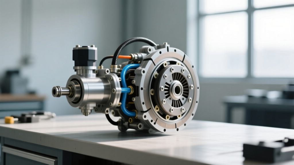
An electric PTO clutch consists of two primary components: the field coil (which houses the copper windings and is bolted to the engine crankshaft) and the armature/rotor assembly (which drives the belt pulley). When you flip the PTO switch on your dashboard, 12 volts are sent to the field coil. This creates a powerful magnetic field that pulls the armature against the coil face, locking them together via friction and transferring engine RPM to the mower blades.
Engagement and disengagement failures generally fall into two categories:
- Electrical Faults: Voltage drops, blown thermal fuses, failed relays, or shorted windings preventing the magnetic field from forming or collapsing.
- Mechanical Faults: Excessive air gap, glazed friction surfaces, or rusted armature plates causing physical slipping or dragging.
Decoding Your Electric PTO Clutch Wiring Diagram
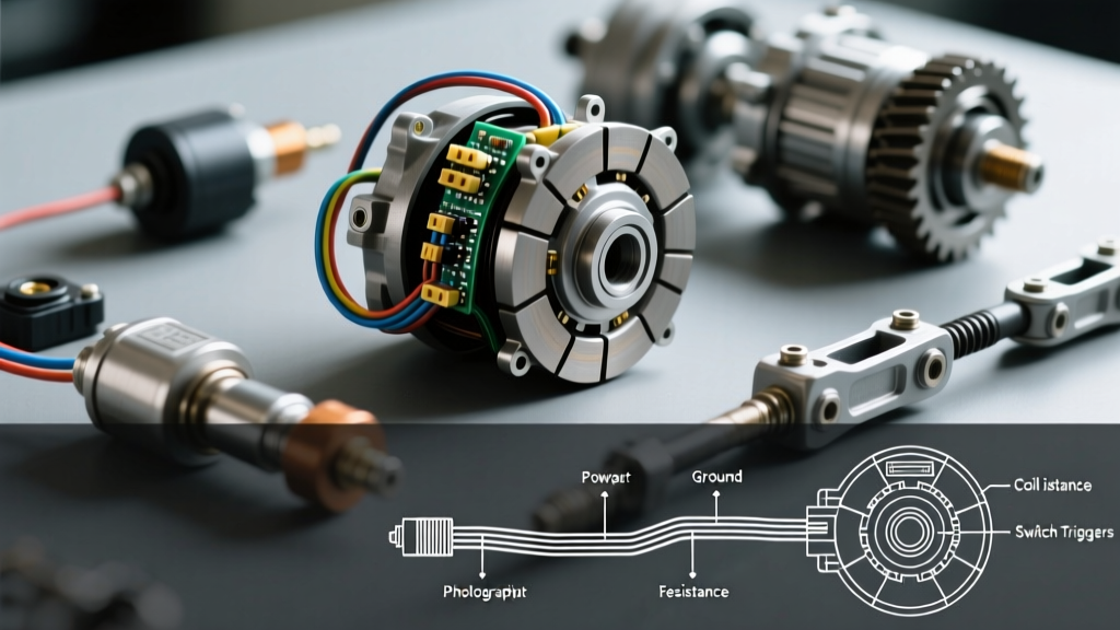
Before touching a multimeter, locate the wiring diagram for your specific equipment (usually found under the seat pan or in the OEM service manual). While schematics vary between brands like John Deere, Toro, and Exmark, the core symbols remain universal. Understanding these symbols is the key to tracing a disengagement or engagement fault.
| Symbol Shape | Component | Function in the PTO Circuit |
|---|---|---|
| Parallel Lines (Long/Short) | 12V Battery | Provides the baseline 12.6V DC power required for the electromagnetic coil. |
| Rectangle with Diagonal Line | PTO Switch / Relay | Acts as the gatekeeper; triggers the high-amperage draw (usually 3-5 amps) to the clutch. |
| Triangle Pointing to a Line | Diode / Brake Module | Crucial for disengagement. Absorbs the voltage spike when the magnetic field collapses, forcing the clutch to release instantly. |
| Zig-Zag Line | Resistor | Often wired in parallel to bleed off residual voltage, preventing the clutch from dragging after the switch is turned off. |
| Circle with Cross | Clutch Coil | The electromagnetic winding that generates the physical clamping force. |
Diagnostic Phase 1: The Clutch Won't Engage
If you flip the switch and hear a faint click from the relay but the blades don't turn—or if you hear nothing at all—the clutch is failing to engage. This is typically caused by a lack of amperage reaching the coil, or an internal break in the coil itself.
Step 1: Perform a Voltage Drop Test
According to voltage drop testing principles, resistance in a wire steals voltage. A PTO clutch requires a minimum of 11.5V under load to generate enough magnetic force to pull the armature across the air gap.
- Set your digital multimeter to DC Volts (20V scale).
- Connect the black probe to the negative battery terminal.
- With the engine running and the PTO switch engaged, pierce the positive wire at the clutch connector with the red probe.
- The Verdict: If you read 12.2V or higher, your wiring is good. If you read 9.5V, you have a corroded connector, a failing relay, or a bad ground wire starving the clutch of the amperage it needs to engage.
Step 2: Test Coil Resistance (Ohms)
If voltage at the plug is perfect, the issue is inside the clutch. Unplug the clutch and set your multimeter to the 200 Ohms (Ω) setting. Place the probes on the two pins of the clutch connector.
- Normal Reading: 2.0 to 4.5 Ohms (Varies by model; a standard Warner Electric 5218-441-002 typically reads around 2.4 Ω).
- Reading 'OL' (Open Loop): The internal copper wire has snapped, or the hidden thermal fuse inside the epoxy potting has blown due to excessive heat. The clutch must be replaced.
- Reading below 1.0 Ohm: The internal windings have shorted together. This will blow your PTO fuse immediately upon engagement.
Diagnostic Phase 2: The Clutch Won't Disengage
A clutch that continues to spin the blades after you turn off the switch is a massive safety hazard. Disengagement issues are rarely caused by the main power wire; instead, they are usually tied to the brake diode module or mechanical drag.
The Role of the Brake Diode
When you cut power to an electromagnetic coil, the collapsing magnetic field generates a massive reverse voltage spike (inductive kickback). If your wiring diagram includes a brake diode or resistor module wired across the positive and negative terminals, its job is to absorb this spike and collapse the field instantly. If this diode fails open, the residual magnetism can keep the armature lightly attracted to the coil face, causing the blades to drag and spin for several seconds after disengagement. Always check the wiring diagram to see if your specific OEM uses an inline resistor module, and test it for continuity if disengagement is delayed.
Mechanical Drag: Rust and Debris
If the electrical side tests perfectly, inspect the physical gap between the coil and the armature. In humid environments, surface rust can form on the machined steel faces. When the power is cut, the rough, rusted surfaces catch on one another, preventing the heavy return springs from pulling the armature away. Lightly sanding the friction faces with 400-grit emery cloth and applying a microscopic layer of anti-seize to the outer splines can cure mechanical dragging.
The Secret Culprit: Air Gap Tolerances
The most common reason for a slipping, overheating PTO clutch that eventually refuses to engage is an out-of-spec air gap. Over time, the friction surfaces wear down. As the gap widens, the magnetic field struggles to bridge the distance. The clutch slips, generating immense heat (often exceeding 300°F), which eventually melts the epoxy holding the copper windings and blows the internal thermal fuse.
As detailed in the engineering specs by Warner Electric, maintaining the precise air gap is mandatory for clutch longevity.
How to Adjust the Air Gap
- Measure: Insert a feeler gauge between the coil face and the armature. The factory specification for almost all 12V commercial PTO clutches is 0.012' to 0.018'. If your gauge reads 0.025' or larger, adjustment is required.
- Locate Adjustment Nuts: Look through the three cutout slots on the side of the clutch. You will see three 3/8' nylock nuts on the adjustment bolts.
- Adjust: Using a 3/8' wrench, turn each nut clockwise (usually 1/4 turn at a time) to pull the armature closer to the coil.
- Verify: Check the gap with your feeler gauge at all three slots. It must be even. An uneven gap will cause the clutch to engage at an angle, leading to immediate warping.
- Torque: Once set to 0.015', tighten the lock nuts to 35-45 in-lbs (inch-pounds, NOT foot-pounds). Overtightening will strip the delicate adjustment threads.
When to Replace: Real Costs and Part Numbers
If your multimeter reads 'OL', or if the friction surfaces are severely scored and the air gap adjustment bolts are maxed out, the clutch is dead. When sourcing replacements, always cross-reference your OEM part number with the clutch manufacturer's direct part number to save money.
- Warner Electric (Altra Industrial Motion): The gold standard for commercial mowers. Part numbers like the 5218-441-002 or 5218-631-003 typically cost between $160 and $240 through aftermarket distributors, compared to $350+ at a branded dealership.
- Ogura Industrial: Known for high-torque, rapid-engagement clutches used in heavy agricultural PTO applications. Check Ogura's PTO lineup for heavy-duty replacements, generally ranging from $200 to $320.
- Xtreme / Hilliard: Common on mid-tier residential tractors. Expect to pay $110 to $150.
By mastering your equipment's electric PTO clutch wiring diagram, you can confidently isolate whether a failure is a $5 relay issue, a free air-gap adjustment, or a $200 clutch replacement. Always trust your multimeter over guesswork, and never ignore the critical brake diode when diagnosing disengagement faults.