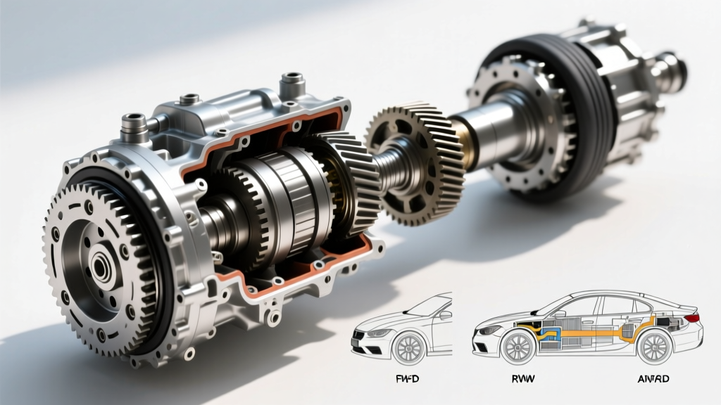
When diagnosing a clunking, vibrating, or squeaking rear-wheel-drive (RWD) or four-wheel-drive (4WD) vehicle, understanding the precise mechanical boundaries of the chassis is critical. Technicians and enthusiasts frequently debate the drivetrain vs powertrain distinction, especially when determining warranty coverage or tracing parasitic power loss. While the powertrain encompasses the engine and the transmission (the components that generate and multiply torque), the drivetrain begins exactly where the powertrain ends: at the transmission output shaft. The drivetrain's sole responsibility is to route that multiplied torque to the drive wheels, navigating suspension articulation and ride-height changes. At the very heart of this torque-transfer network sits the universal joint (U-joint).
The Boundary Line: Drivetrain vs Powertrain Explained
To effectively troubleshoot U-joint symptoms, we must first establish the mechanical border between the two systems. The powertrain includes the engine block, cylinder heads, internal rotating assemblies, torque converter, clutch, and the transmission's internal gear sets and valve bodies. If a 6L80 or ZF 8HP transmission slips in third gear, that is a powertrain failure.
Conversely, the drivetrain comprises the transfer case (in 4WD/AWD applications), the driveshaft, the U-joints, the constant velocity (CV) joints, the differential, and the axle shafts. A failing U-joint is strictly a drivetrain malfunction. This distinction is vital not only for mechanical diagnosis but also for navigating manufacturer warranties, which often cover the powertrain for 100,000 miles but limit drivetrain coverage to 60,000 miles or less. Because U-joints are classified as wearable driveline components, they are rarely covered under extended powertrain warranties once the initial bumper-to-bumper period expires, leaving the repair cost squarely on the owner.
Anatomy of Universal Joint Failure
A standard cross-and-roller U-joint consists of a forged steel cross (or spider), four trunnions, needle bearings, bearing caps, and snap rings. The needle bearings allow the driveshaft to operate at an angle while transmitting rotational force. Failure rarely happens catastrophically without warning; it is a progressive degradation of metallurgical tolerances and lubrication.
Primary Failure Modes
- Brinelling: This occurs when the needle bearings are subjected to heavy shock loads without adequate rotation, causing them to press permanent indentations into the bearing cap race. It is common in heavily loaded tow rigs and off-road vehicles.
- Seal Extrusion: The rubber or polyurethane cap seals are designed to retain grease and expel water. When subjected to excessive heat, over-greasing via a zerk fitting, or extreme driveline angles, the seal lip rolls or tears, allowing moisture ingress and rapid rust formation.
- Galling and Spalling: Once the grease breaks down or water contaminates the needle bearings, metal-on-metal friction causes microscopic tearing (galling) and eventual flaking (spalling) of the hardened steel surfaces.
Diagnostic Matrix: U-Joint Symptoms vs. Other Driveline Faults
Misdiagnosing a U-joint is a common pitfall. A vibration at 65 mph could easily be a tire balance issue, a bent axle flange, or a failing carrier bearing. Use the following diagnostic matrix to isolate U-joint-specific symptoms from other drivetrain anomalies.
| Symptom | U-Joint Fault Profile | Alternative Drivetrain/Powertrain Culprit |
|---|---|---|
| Metallic 'Clunk' on Gear Engagement | Excessive clearance between worn trunnions and needle bearings; cap movement in the yoke. | Excessive differential backlash; worn transmission output shaft spline. |
| Cyclic Squeak (Speed Dependent) | Dry, rusted needle bearings lacking lubrication; often heard at 10-25 mph before fading at highway speeds. | Dry slip-yoke splines; binding parking brake shoes. |
| High-Speed Vibration (55-75 mph) | Severe brinelling causing the joint to bind and unbind, creating secondary driveline harmonics. | Out-of-balance driveshaft; worn center carrier bearing; bent axle shaft. |
| Shudder on Heavy Acceleration | Operating angles exceeding 3 degrees combined with joint wear, causing unequal velocity cancellation failure. | Worn engine/transmission mounts; failing torque converter clutch (TCC). |
Spicer U-Joint Series: Sizing and Torque Specifications
Dana Spicer remains the gold standard for light-duty and heavy-duty U-joints in the North American market. Selecting the correct series is dictated by the vehicle's gross weight, torque output, and yoke dimensions. Below are the critical specifications for the most common drivetrain applications, ranging from half-ton pickups to heavy-duty diesel trucks.
| Spicer Series | Cap Diameter | Cross Width (Lock-to-Lock) | Common Applications | Strap Bolt Torque Spec |
|---|---|---|---|---|
| 1310 | 1.062' | 3.219' | Jeep Wrangler, F-150, Half-ton SUVs | 15 - 20 lb-ft |
| 1350 | 1.188' | 3.622' | F-250 Gas, Silverado 2500, Heavy SUVs | 20 - 25 lb-ft |
| 1410 | 1.188' | 4.188' | F-350 Diesel, Ram 3500, 1-Ton Axles | 25 - 30 lb-ft |
| 1480 | 1.313' | 4.188' | Heavy Commercial, High-HP Off-Road | 30 - 35 lb-ft |
Note: Always refer to the specific OEM service manual for your vehicle, as some manufacturers utilize proprietary flange bolts or stover nuts that require different torque values and one-time-use stretch hardware.
Step-by-Step Replacement Protocol
Replacing a U-joint requires precision. Hammering on the bearing caps with a steel drift is a relic technique that risks deforming the driveshaft yoke ears, leading to permanent driveline vibration. A proper replacement demands a dedicated U-joint press tool (such as the OTC 7248 or a 12-ton hydraulic shop press with appropriate cup adapters).
1. Extraction and Yoke Inspection
Remove the driveshaft and mark the orientation of the yokes relative to the slip spline and differential flange to preserve factory phasing. Remove the external snap rings (or internal clips, depending on the application). Using the press tool, apply steady hydraulic pressure to push one cap through the cross while the opposite cap is pushed out into the receiving cup. Critical Check: Once the cross is removed, inspect the yoke ears for elongation. If the cap bores measure more than 0.002 inches over the factory specification, the driveshaft yoke is compromised and the entire shaft must be rebuilt or replaced.
2. Cross and Cap Preparation
If utilizing a greaseable aftermarket joint, pre-fill the cross cavity with a high-quality NLGI Grade 2 Lithium-Complex or Moly-fortified grease before installing the caps. This ensures the needle bearings are immediately protected upon startup. Carefully start the new caps into the yoke ears by hand or with light taps from a brass drift to avoid cocking the needle bearings, which will instantly destroy the cap seal.
3. Seating and Snap Ring Installation
Press the caps inward until the snap ring grooves are fully exposed. Install the snap rings. To ensure the caps are fully seated against the snap rings (eliminating 'play' that causes clunking), strike the yoke ears sharply on the flat sides with a brass or dead-blow hammer. Re-check the snap rings; if they were previously difficult to install, they should now slip into the grooves with minimal effort using snap-ring pliers.
The Phasing and Operating Angle Trap
A frequent complaint after a U-joint replacement is the emergence of a new, high-frequency vibration. This is rarely a defective part; it is almost always an issue with driveline phasing or operating angles. According to driveline engineering principles outlined by Tremec's technical resources, U-joints do not transmit velocity at a constant rate when operating at an angle. They accelerate and decelerate twice per revolution.
To cancel out this non-uniform velocity, the front and rear U-joints must be 'in phase'—meaning the yokes on both ends of the driveshaft are aligned in the exact same plane. Furthermore, the operating angles at the transmission output and the differential pinion must be equal and opposite (typically between 1 and 3 degrees). If a lifted vehicle has had its control arms or leaf springs modified without installing adjustable control arms or shimmed leaf blocks, the pinion angle will be misaligned, forcing the U-joints to operate outside their cancellation parameters. This results in severe cyclic vibrations that will quickly destroy even a brand-new, heavy-duty Spicer 1410 joint.
Maintenance: Lubrication Realities
While many modern OEM drivetrains utilize 'sealed-for-life' U-joints, aftermarket and heavy-duty replacements often feature zerk fittings. Over-greasing is a primary cause of premature failure. Pumping grease until the cap seals bulge will stretch the polyurethane lip, allowing dirt and water to enter the bearing cavity. The correct procedure is to pump grease only until you feel slight resistance and see the seal lip just barely begin to weep a micro-bead of fresh grease. For vehicles subjected to water fording or heavy mud, this interval should not exceed 5,000 miles, utilizing a water-resistant marine or moly-fortified grease to displace moisture and prevent the brinelling associated with dry, shock-loaded needle bearings.
By respecting the mechanical boundary where the powertrain ends and the drivetrain begins, and by adhering to strict torque specs and angle tolerances, you can eliminate driveline harmonics and ensure reliable torque delivery to the pavement.