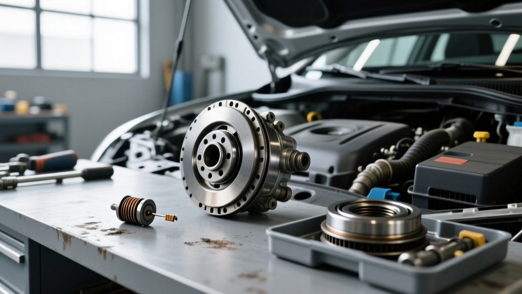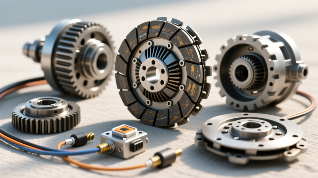
The Nightmare of Intermittent Clutch Faults
Intermittent clutch problems represent one of the most frustrating diagnostic challenges in modern manual transmission vehicles. A vehicle that starts perfectly on Tuesday but experiences a no-crank condition on Wednesday, or cruise control that randomly disengages on the highway without storing a hard diagnostic trouble code (DTC), often points to the clutch pedal position (CPP) circuit. In an era where 2025 and 2026 model-year manual vehicles rely heavily on CAN bus networks for auto start-stop functionality and rev-matching algorithms, the clutch switch is no longer just a simple mechanical breaker. It is a critical data input for the Powertrain Control Module (PCM) and Body Control Module (BCM).
Before immediately proceeding with a clutch switch replacement, technicians and advanced DIYers must perform a systematic intermittent clutch problems diagnosis. Replacing the switch without verifying the mechanical pedal linkage, wiring harness integrity, or BCM logic can lead to misdiagnosed repairs and recurring faults. This guide details the exact diagnostic protocols, electrical testing parameters, and mechanical edge cases required to accurately isolate intermittent clutch switch failures.
Dual-Switch Architecture in Modern Manuals
To diagnose the issue, you must first understand the architecture. Modern manual transmissions—such as the Tremec T56 Magnum F found in late-model Camaros, the Ford MT-82, and the Honda 6-speed units in the Civic Type R—utilize a dual-switch or multi-sensor setup at the pedal bracket.
1. The Clutch Interlock Switch (Starter Circuit)
This is a normally open (NO) switch that closes when the pedal is fully depressed. It completes the ground circuit for the starter relay. An intermittent no-crank condition is the hallmark symptom of a failing interlock switch, often caused by internal contact pitting or a worn pedal stop-bumper that prevents full actuation.
2. The Clutch Position Sensor (PCM/Cruise/Start-Stop)
Often a Hall-effect sensor or a variable resistor, this component provides real-time pedal position data to the PCM. The PCM uses this data to disengage cruise control, enable auto rev-matching on downshifts, and manage the auto start-stop system. Intermittent voltage drops here will cause cruise control dropout, erratic idle when shifting, and start-stop disablement.
Symptom-to-Root-Cause Diagnostic Matrix
Use the following matrix to narrow down your diagnostic path before ordering parts. Accurate symptom mapping prevents unnecessary clutch switch replacement when the root cause lies elsewhere.
| Intermittent Symptom | Primary Suspect | Diagnostic Verification Step |
|---|---|---|
| Random No-Crank / Starter Click | Interlock Switch or Pedal Bumper | Check continuity at starter relay Pin 85 while manipulating pedal. |
| Cruise Control Random Dropout | CPP Sensor or Wiring Chafe | Monitor PID 'CLTCH_SW' via scan tool during road test. |
| Reverse Lights Flickering | Transaxle Reverse Light Switch | Bypass switch at transmission housing; check for gear oil contamination. |
| Auto Start-Stop Fails to Engage | Dual CPP Sensor Mismatch | Compare Sensor A and B voltage curves for dead spots. |
| Rev-Match Failure on Downshift | CPP Sensor Calibration / BCM | Verify pedal travel percentage via bi-directional scan tool. |
Step-by-Step Intermittent Diagnosis Protocol
When a vehicle presents with an intermittent clutch fault, follow this exact sequence to isolate the failure point.
- Scan Tool Live Data Analysis: Connect a bi-directional scan tool and navigate to the PCM data stream. Locate the Clutch Pedal Position PID. Slowly depress and release the pedal. The percentage should sweep smoothly from 0% to 100%. If the data stream shows sudden drops (e.g., jumping from 45% to 12% and back), you have either a failing Hall-effect sensor or a wiring short.
- Mechanical Linkage Inspection: A highly common, often overlooked cause of intermittent issues is the degradation of the plastic pedal stop-bumper. For example, on GM platforms (part #15154886), this rubber/nylon bumper crumbles over time. If the bumper is missing, the pedal over-travels, and the switch plunger bottoms out or misaligns, causing intermittent contact. Always inspect the physical pedal travel before testing the electrical circuit.
- Voltage Drop and Wiggle Test: Set your digital multimeter (DMM) to DC Volts. Back-probe the signal wire at the CPP sensor connector. With the key on, engine off (KOEO), the voltage should read a steady 5V reference or 12V battery voltage (depending on the OEM circuit design). While monitoring the DMM, aggressively wiggle the wiring harness from the pedal bracket up to the firewall grommet. A sudden voltage drop indicates a broken copper strand inside the insulation—a common failure point due to the constant flexing of the harness.
- Connector Micro-Corrosion Check: Disconnect the switch connector and inspect the terminals. Fretting corrosion (a white or green powdery residue) increases circuit resistance. The BCM monitors this resistance; if it fluctuates, the module will intermittently disable the start-stop system and set a soft U-code (network communication fault).
When Clutch Switch Replacement is the Correct Fix
If the mechanical linkage is sound, the wiring harness passes the wiggle test, and the scan tool data confirms erratic internal sensor behavior, a clutch switch replacement is required. According to industry data from Standard Motor Products (SMP) and Dorman Products, these switches are subject to high cycle fatigue, often failing between 60,000 and 90,000 miles.
Part Numbers, Pricing, and Labor
- GM/Chevrolet (Camaro/Corvette): Dorman 924-951 or ACDelco D1443C. Retail price: $18 - $32.
- Ford (Mustang MT-82): Motorcraft SW-6356. Retail price: $25 - $45.
- Labor Time: Book time is typically 0.3 to 0.5 hours ($45 - $75 at independent shop rates).
Crucial Torque Specifications and Calibration
Improper installation of the new switch will immediately result in recurring intermittent faults. The switch mounting bracket and pedal hardware must be secured to exact OEM specifications.
- Switch Mounting Bolts (M6): Torque to 8 - 10 Nm (71 - 88 lb-in). Overtightening will crack the plastic housing, leading to moisture ingress and premature failure.
- Pedal Bracket Nuts (M8): Torque to 15 - 20 Nm (11 - 15 lb-ft).
- Pushrod Locknut (if adjustable): Torque to 5 - 7 Nm. Ensure exactly 1-2mm of free-play exists between the switch plunger and the pedal pad to prevent the switch from being constantly pre-loaded, which destroys the internal spring.
Calibration Note: On modern drive-by-wire clutch systems and vehicles with advanced auto start-stop (such as the 2024-2026 Mazda3 and VW Golf GTI manuals), a CPP sensor relearn procedure via a bi-directional scan tool is mandatory after replacement. The PCM must relearn the top-dead-center and bottom-dead-center voltage thresholds. Skipping this step will result in harsh rev-matching and start-stop errors.
Advanced Edge Cases: Wiring and BCM Logic
Occasionally, the switch itself is perfectly functional, but the vehicle still exhibits intermittent clutch problems. Two advanced edge cases must be considered:
1. Firewall Grommet Water Ingress
The wiring harness passes through a rubber grommet at the firewall. If this grommet is torn or improperly seated after an aftermarket stereo or alarm installation, water from the cowl area drains directly onto the CPP switch connector. This causes intermittent shorting only during heavy rain or car washes. Always apply a high-quality dielectric grease (e.g., Permatex 22058) to the connector terminals during reassembly to displace moisture.
2. BCM Logic and Aftermarket Accessories
According to safety guidelines monitored by the National Highway Traffic Safety Administration (NHTSA), the clutch interlock is a critical safety device. If aftermarket accessories (like remote starters or alarm bypass modules) are spliced into the clutch interlock wire using cheap T-taps, the added resistance and micro-movements of the T-tap connection will cause intermittent no-crank scenarios. Always trace the wiring back to the BCM to check for unauthorized splices if the OEM switch tests perfectly.
Pro-Tip for Diagnostics: Never use a standard test light on modern CAN bus-controlled clutch position sensors. The high current draw of a test light can back-feed voltage into the PCM's delicate 5-volt reference circuit, potentially frying the internal driver. Always use a high-impedance Digital Multimeter (DMM) or an automotive logic probe.
Summary
Intermittent clutch problems diagnosis requires a methodical approach that bridges mechanical inspection and electrical diagnostics. While a clutch switch replacement is a common and relatively inexpensive fix (typically under $50 in parts), it is only the correct solution if the mechanical pedal stops are intact, the wiring harness is free of flex-fractures, and the connector terminals are free of fretting corrosion. By leveraging live scan tool data, performing rigorous voltage drop tests, and adhering to precise torque and calibration specifications, you can permanently resolve intermittent starting, cruise control, and rev-matching faults on modern manual transmission vehicles.