The Anatomy of Hydraulic Clutch Actuation
When diagnosing manual transmission drivability issues, technicians and enthusiasts alike must trace the path of mechanical force from the driver's foot to the pressure plate. Understanding what ultimately pushes on the clutch release bearing to operate the clutch is the first step in mastering hydraulic system diagnostics. Unlike older cable-actuated systems that suffered from stretch, friction, and snapping, modern hydraulic setups rely on incompressible fluid to transfer pedal effort with surgical precision. However, as of 2026, the increasing complexity of concentric slave cylinders (CSC) and high-pressure hydraulic lines has introduced new failure modes that require strict preventive maintenance.
In a standard hydraulic layout, pressing the pedal moves a pushrod that actuates the master cylinder piston. This forces DOT-rated brake fluid through a hard line, transitioning into a flexible hose, and finally into the slave cylinder. The slave cylinder's piston then extends, pushing a mechanical fork (in external setups) or directly engaging the bearing sleeve (in concentric setups) to compress the pressure plate diaphragm springs. If any component in this sealed hydraulic loop degrades, the bearing fails to receive the necessary force, resulting in incomplete disengagement, gear grind, or premature bearing wear.
The Physics of Hydraulic Line Pressure
To diagnose clutch symptoms accurately, you must understand the immense pressures at play. A standard daily-driver clutch pedal generates roughly 80 to 120 pounds of foot effort. Through the pedal ratio (typically 6:1 to 8:1) and the master cylinder bore diameter (usually 5/8-inch or 15.87mm), this translates to hydraulic line pressures ranging from 800 to 1,200 PSI. In high-performance applications featuring twin-disc clutches (like the McLeod RST or Tilton 7.25-inch), line pressures can spike beyond 1,800 PSI.
At these pressures, microscopic internal bypassing in the master cylinder or slight ballooning of degraded rubber flex hoses will rob the slave cylinder of the stroke required to fully push on the clutch release bearing to operate the clutch. This is why a pedal that feels 'firm' but fails to disengage the transmission is a classic hallmark of internal hydraulic bypass or hose expansion.
Hydraulic Clutch Diagnostic Matrix
Use the following diagnostic matrix to isolate hydraulic faults from mechanical transmission failures before tearing down the bellhousing.
| Symptom | Primary Hydraulic Culprit | Mechanical Edge Case | Preventive Fix / Test |
|---|---|---|---|
| Spongy Pedal / Low Engagement Point | Air ingress via porous rubber flex hose or loose bleeder | Worn clutch pivot ball or bent release fork | Pressure bleed at 15 PSI; inspect hose for micro-blisters |
| Pedal Sinking to Floor Under Load | Internal master cylinder cup bypass (fluid leaking past piston) | Overheated clutch fluid boiling into vapor (vapor lock) | Clamp off hard line; if pedal holds, master cylinder is defective |
| Incomplete Disengagement (Gear Grind) | Slave cylinder stroke loss due to line expansion or internal leak | Warped clutch disc, broken damper springs, or worn pilot bearing | Measure slave pushrod travel (spec: 12mm-18mm); upgrade to braided line |
| Notchy Pedal Return / Sticking | Contaminated fluid swelling master cylinder rubber seals | Binding release bearing on transmission input shaft collar | Flush system with DOT 4; inspect master pushrod freeplay (0.1-0.5mm) |
Preventive Maintenance: Fluid Chemistry and Intervals
Clutch fluid is frequently neglected because it is often tucked away in a separate, smaller reservoir or shared with the brake system. Most OEMs specify DOT 3 or DOT 4 fluid. Because these glycol-ether-based fluids are highly hygroscopic, they absorb ambient moisture through microscopic pores in the rubber hoses and reservoir cap diaphragms.
The Boiling Point Threat
According to AA1Car's technical archives, moisture contamination drastically lowers the fluid's boiling point. Fresh DOT 4 fluid boasts a dry boiling point of 446°F (230°C), but at just 3.7% water content, the wet boiling point plummets to 311°F (155°C). In heavy stop-and-go traffic or track environments, heat transfer from the bellhousing and exhaust can easily boil contaminated fluid, creating compressible gas bubbles that entirely eliminate the hydraulic force needed to push on the clutch release bearing to operate the clutch.
- Standard Interval: Flush every 2 years or 30,000 miles.
- Performance Interval: Annually, upgrading to a high-temp DOT 5.1 or racing fluid like Motul RBF 600 (Dry BP: 617°F / 325°C).
- Mineral Oil Warning: Never mix DOT fluids with mineral-based hydraulic fluids (e.g., LHM used in classic Citroens or specific BMW applications). Mixing will instantly destroy the EPDM rubber seals in the master and slave cylinders.
Bleeding Protocols and Critical Torque Specifications
A proper bleed is the cornerstone of hydraulic clutch preventive maintenance. Gravity bleeding is rarely sufficient for modern systems due to the complex routing of hydraulic lines and the upward angle of many slave cylinder bleeder valves, which trap air.
- Preparation: Use a 10mm, 11mm, or 12mm flare-nut wrench to prevent rounding the soft brass or steel bleeder screw. Apply penetrating fluid 24 hours prior.
- Pressure Bleeding: Connect a pneumatic pressure bleeder (e.g., Motive Products 0108) to the master reservoir. Set the pressure to 12-15 PSI. Higher pressures can rupture the master cylinder diaphragm or blow out the slave cylinder piston seals.
- Opening the Valve: Open the slave bleeder screw until fluid flows clear and bubble-free. Torque spec: When closing, most M8x1.0 or M10x1.0 bleeder valves require only 8 to 12 Nm (70-106 lb-in). Over-torquing will snap the valve inside the slave cylinder body, ruining the component.
- Pushrod Verification: After bleeding, verify the master cylinder pushrod clearance. There must be 0.1mm to 0.5mm of freeplay between the pushrod and the master piston. Zero clearance will block the compensating port, causing fluid pressure to build as the engine bay heats up, inadvertently applying the clutch and causing catastrophic slip.
Concentric vs. External Slave Cylinders: Maintenance Realities
The physical location of the slave cylinder dictates the severity of the maintenance required. As detailed in Schaeffler's aftermarket clutch engineering guides, the industry has heavily shifted toward Concentric Slave Cylinders (CSC) to reduce rotational mass and improve packaging in tight engine bays.
External Slave Cylinders (e.g., GM T56 Magnum, Honda K-Series)
External slaves mount on the outside of the bellhousing and actuate a traditional release fork. They are easily accessible, inexpensive, and simple to bleed.
- Part Example: Sachs SH5005 (Honda S2000 / Civic Si)
- Replacement Cost: $45 - $90 for the part.
- Labor Time: 0.5 to 1.0 hours.
- Preventive Tip: Upgrade the OEM rubber flex hose to a Goodridge or Russell braided stainless steel line to eliminate hose expansion under high pedal effort.
Concentric Slave Cylinders (e.g., Ford MT-82, ZF S6-650, BMW GS6-45BZ)
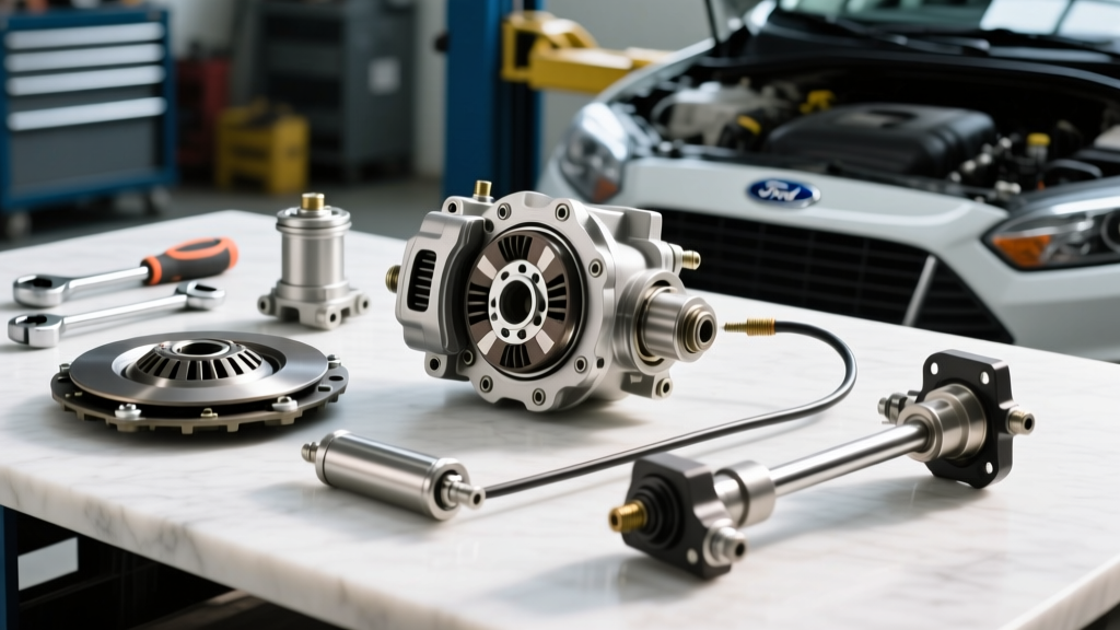
A CSC mounts directly on the transmission input shaft, encircling it. The piston face directly pushes on the clutch release bearing to operate the clutch, eliminating the pivot ball and fork. While this provides superior pedal feel and exacting alignment, a CSC leak or failure requires complete transmission removal.
- Part Example: LuK LSC 510 0115 10 (Ford Mustang MT-82)
- Replacement Cost: $120 - $280 for the CSC unit.
- Labor Time: 4.5 to 7.0 hours (Requires dropping the exhaust, driveshaft, and transmission).
- Total Shop Bill: $800 - $1,500+ depending on regional labor rates.
- Preventive Tip: Because labor is so intensive, never replace a clutch disc and pressure plate without simultaneously installing a brand-new CSC. Reusing an old CSC with a new clutch is a false economy that risks a $1,000 labor bill for a $150 part failure months later.
Upgrading for Longevity: Reservoirs and Hard Lines
For vehicles subjected to track use or heavy towing, preventive maintenance extends beyond fluid swaps. The OEM plastic clutch reservoirs are prone to cracking at the hose barb due to heat cycling and engine vibration. Upgrading to an aluminum billet reservoir (such as those offered by Vibrant Performance or specialty OEM suppliers) ensures a robust seal. Furthermore, inspecting the hard line routing is critical; ensure the hydraulic line is not touching the exhaust manifold or catalytic converter, as radiant heat will rapidly degrade the fluid and cause localized boiling.
Summary
Diagnosing clutch actuation issues requires a methodical approach that separates hydraulic faults from mechanical wear. By understanding the immense fluid pressures involved, adhering to strict 2-year fluid flush intervals, utilizing proper torque specs on delicate bleeder valves, and acknowledging the labor realities of concentric slave cylinders, you can ensure the hydraulic system reliably pushes on the clutch release bearing to operate the clutch for hundreds of thousands of miles. Preventive maintenance is always cheaper than a stranded vehicle and a dropped transmission.