Introduction: The Complexity of AWD Power Distribution
In the modern automotive landscape of 2026, All-Wheel Drive (AWD) systems have evolved from rudimentary mechanical lockers to highly sophisticated, computer-managed torque-vectoring networks. However, the mechanical heart of any true full-time AWD system remains the center differential. When driveline symptoms arise—ranging from low-speed corner binding to high-speed shuddering—technicians and advanced DIYers must rely on a precise differential axle diagram to trace power flow, identify failure points, and prescribe the correct fluid or mechanical intervention.
Unlike a standard front or rear open differential, the center differential manages the speed differential between the front and rear axles. Misdiagnosing a center diff issue often leads to unnecessary transmission removals or misdirected suspension work. This guide will decode the visual and mechanical language of center differential schematics, providing actionable diagnostic pathways for the most common AWD architectures.
Decoding the Differential Axle Diagram for Center Diffs
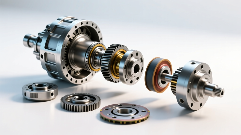
When you pull up a factory service manual or an aftermarket differential axle diagram for an AWD transfer case, you are looking at a cross-sectional map of torque routing. Understanding this map is critical for isolating symptoms.
Tracing Power Flow in Torsen vs. Viscous Designs
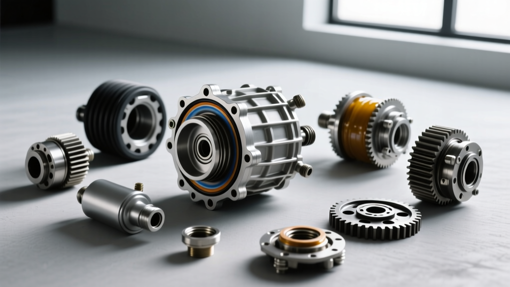
In a gear-driven Torsen (Torque Sensing) center differential, commonly found in Audi Quattro and certain Toyota 4WD systems, the diagram will highlight an epicyclic gear set featuring helical worm gears and worm wheels. Power enters via the transmission output shaft into the differential housing. From there, it splits through the worm gears to the front and rear output shafts. If your diagram shows thrust washers and helical gear pockets, you are dealing with a purely mechanical, torque-biasing unit that requires no specialized friction-modified fluid, but is highly susceptible to thrust washer wear and gear scoring if starved of lubrication.
Conversely, a Subaru Symmetrical AWD diagram featuring a viscous center differential will show a sealed cylindrical coupler containing interleaved inner and outer clutch plates suspended in a silicone-based shear fluid. The diagram will not show traditional spider gears; instead, it will illustrate the inner shaft connected to the front output and the outer housing connected to the rear output. Recognizing this visual distinction on the schematic immediately tells the diagnostician that corner-binding issues are likely tied to fluid degradation rather than gear tooth failure.
Symptom Diagnosis: 3 Common Center Differential Failures
By correlating the physical components shown on your differential axle diagram with real-world driving symptoms, you can accurately pinpoint the root cause of driveline distress.
1. Low-Speed Corner Binding (Multi-Plate Clutch Glazing)
The Symptom: The vehicle exhibits severe "hopping" or binding in the driveline during tight, low-speed maneuvers (e.g., pulling into a parking space), often accompanied by a clunking noise from the center tunnel.
Diagram Correlation: The schematic for a multi-plate clutch center diff (like Subaru’s DCCD or electronically controlled transfer cases) shows alternating friction and steel plates bathed in fluid. The Diagnosis: This is almost always caused by the depletion of friction modifiers in the gear oil, leading to clutch plate glazing. When the plates cannot slip smoothly during the speed differentiation required for cornering, they grab and release violently. The Fix: Perform a complete drain and fill using an OEM-specified fluid with the correct friction modifier package. For Subaru applications, this means using Subaru Extra-HP 75W-90 GL-5 or an equivalent synthetic with high friction-modifier retention. If a fluid swap fails, the clutch pack is physically warped and requires a teardown.
2. High-Speed Driveline Shudder (Viscous Coupler Hump)
The Symptom: A rhythmic vibration or shudder felt through the chassis at highway speeds (65-80 mph), which disappears when the vehicle is driven in a straight line at low speeds or when the center diff is manually locked (if equipped).
Diagram Correlation: The viscous coupler diagram highlights the tight tolerances between the inner and outer plate arrays. The Diagnosis: This phenomenon, known in tribology as the "hump effect," occurs when the silicone fluid inside the viscous coupler degrades over time and thermal cycling. The fluid loses its predictable shear-rate viscosity, causing the coupler to rapidly cycle between slipping and locking at high rotational speeds. The Fix: Viscous couplers are sealed, welded units. They cannot be serviced or refilled. The entire center differential assembly must be replaced. Expect to pay between $800 and $1,400 for an OEM replacement unit in 2026.
3. Torque Bias Loss & AWD Warning Lights (Helical Gear Wear)
The Symptom: The vehicle behaves like a FWD or RWD car under hard acceleration on low-traction surfaces, and the AWD/ABS warning light may illuminate due to unexpected wheel speed sensor discrepancies.
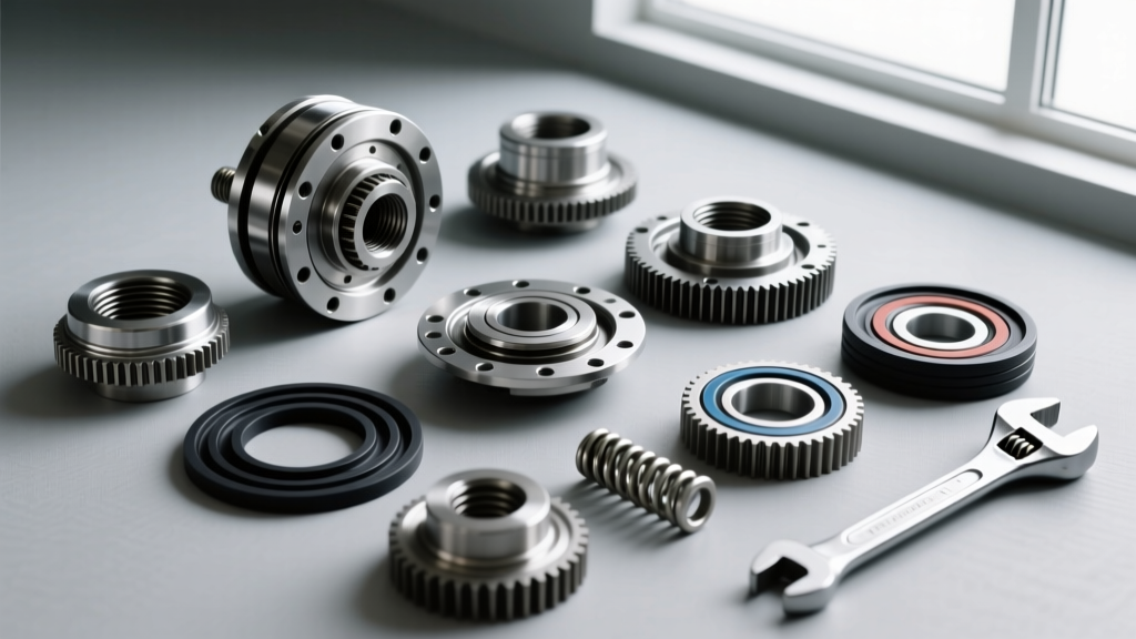
Diagram Correlation: A Torsen Type C or Crown Gear diagram illustrates the reliance on axial thrust generated by helical gears pressing against thrust washers to create the internal friction necessary for torque biasing. The Diagnosis: If the thrust washers wear down, or if the wrong fluid (lacking extreme pressure additives) is used, the helical gears cannot generate sufficient axial thrust. The differential essentially becomes an open diff, sending 100% of the torque to the axle with the least resistance (the slipping wheels). The Fix: Teardown and measurement. If the thrust washers are worn beyond the 0.15mm tolerance, a rebuild kit (typically $400-$600) is required. Always refill with the exact OEM fluid, such as ZF specified synthetic gear oils, to restore the necessary coefficient of friction.
2026 OEM Fluid Specifications & Torque Data
Using the incorrect fluid is the number one cause of premature center differential failure. Referencing the service manual alongside your differential axle diagram ensures you match the fluid chemistry to the mechanical design.
| AWD System / Vehicle | Center Diff Type | OEM Fluid Specification | Capacity | Drain/Fill Torque |
|---|---|---|---|---|
| Subaru WRX / STI (Manual) | Viscous / Multi-plate (DCCD) | Subaru Extra-HP 75W-90 GL-5 | ~3.7 Liters (Total) | 33 lb-ft (45 Nm) |
| Audi B8/B9 Quattro (Manual/ZF Auto) | Torsen / Crown Gear | G 055 145 A2 / G 052 145 A2 | 0.8 - 1.1 Liters | 25 Nm (18.5 lb-ft) |
| Toyota GR Yaris / GR Corolla | Torsen (High Friction) | Toyota Genuine Hypoid Gear Oil SX 75W-85 | ~0.45 Liters (Center) | 29 lb-ft (39 Nm) |
Step-by-Step Diagnostic Workflow
When a customer complains of AWD driveline noise or binding, follow this systematic approach using your differential axle diagram as a reference:
- Step 1: The Figure-8 Test. Drive the vehicle in a tight figure-8 pattern on dry pavement at 5 mph. Listen for binding or hopping. If present, suspect multi-plate clutch glazing or a locked viscous coupler.
- Step 2: The Chassis Dyno Slip Test. Safely elevate the vehicle or use a dyno. Spin one rear wheel while holding the front wheels stationary. A functioning Torsen diff will transfer torque and spin the front wheels or the opposite rear wheel. An open/failing center diff will simply spin the single wheel indefinitely.
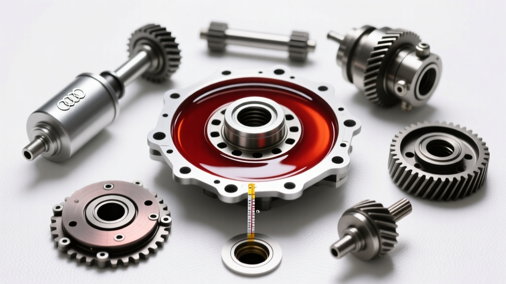
- Step 3: Fluid Sampling. Drain a small sample of the center diff fluid. Look for metallic glitter (indicating gear or thrust washer wear) or a burnt smell (indicating clutch pack overheating). Compare the fluid routing on your diagram to ensure you are draining the correct center chamber, not the rear hypoid gear set.
- Step 4: Electronic Interrogation. For electronically managed center diffs (like Haldex Gen 5 or modern active torque couplings), scan the AWD control module for clutch pressure sensor faults or pump cavitation codes before condemning the mechanical hardware.
"Never assume a center differential failure is internal until you have verified the health of the peripheral driveline. A worn rear driveshaft center support bearing or a mismatched tire circumference can mimic center diff binding perfectly. Always measure tire rolling circumference before tearing into the transfer case."
Repair Economics: Rebuild vs. Replace in 2026
The decision to rebuild or replace a center differential hinges on the architecture shown in your differential axle diagram. Viscous and sealed multi-plate units are generally non-serviceable; OEM replacement assemblies range from $1,200 to $2,800 depending on the marque. Conversely, gear-driven Torsen and open planetary center diffs can often be rebuilt. A master rebuild kit—including new bearings, seals, thrust washers, and friction clutches—typically costs between $350 and $750. However, the specialized labor required to set gear backlash and preload in an AWD transfer case can add $800 to $1,500 to the final invoice. For high-mileage daily drivers, a remanufactured unit with a warranty is often the most economically sound choice.
By mastering the interpretation of the differential axle diagram, technicians can bypass guesswork, accurately diagnose complex AWD symptoms, and restore optimal torque distribution to the pavement.