Introduction: The Evolution of CVT Launch Mechanisms
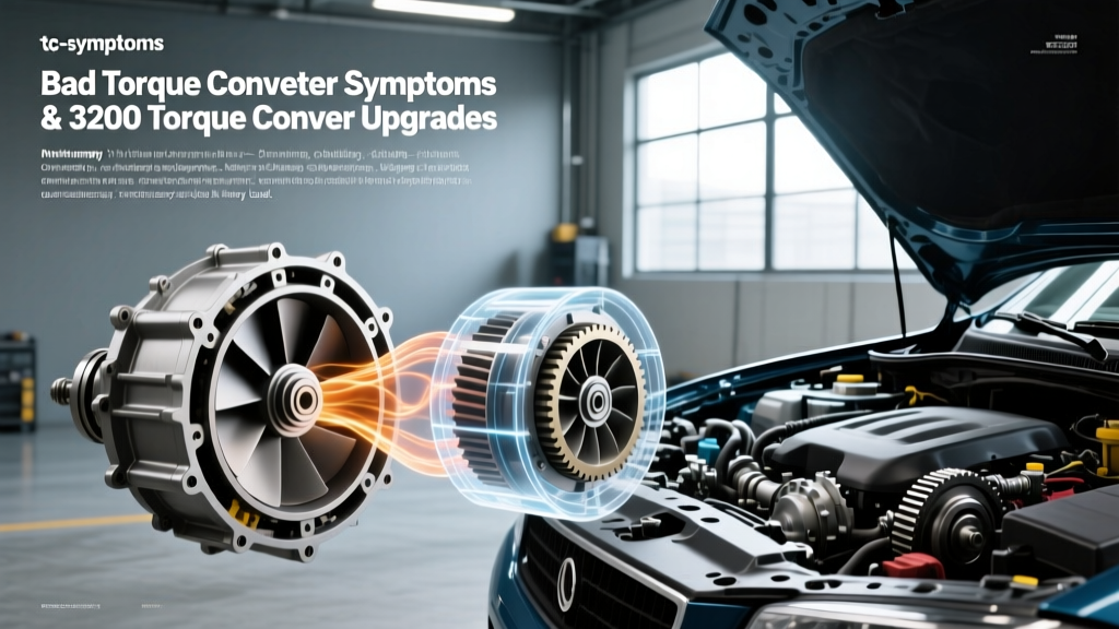
A persistent myth in the automotive repair industry is that Continuously Variable Transmissions (CVTs) do not utilize torque converters. While early-generation CVTs relied exclusively on wet start clutches or electromagnetic clutches to initiate vehicle movement, modern high-torque CVTs have evolved. As of 2026, manufacturers like Honda, Toyota, and newer iterations of Jatco and GM CVT platforms frequently employ specialized, miniaturized torque converters. These units are designed to multiply engine torque during launch and isolate torsional vibrations before they can damage the delicate steel belt and variator pulley assemblies.
To properly diagnose launch shudder, slip, or lockup issues in these modern systems, technicians must understand how they differ from traditional heavy-duty automatic setups. In this step-by-step guide, we will contrast the diagnostic procedures for modern CVT torque converters against the benchmark GM55 torque converter—a common industry and aftermarket designation for the heavy-duty 300mm diameter, 55mm hub converters used in GM’s 5.3L V8 rear-wheel-drive platforms (such as the 6L80 and 8L90 transmissions).
Traditional vs. CVT: Understanding the Baseline
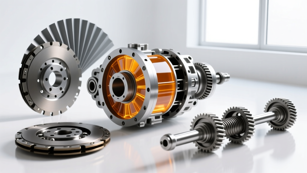
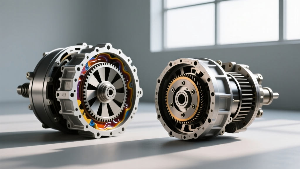
Before grabbing a scan tool, it is critical to understand the mechanical intent of the hardware you are working on. The traditional GM55 torque converter is built for high-torque towing and aggressive lockup. It features a robust stator, a heavy-duty turbine damper, and a centrifugal pendulum absorber (CPA) to handle the massive low-end torque of a 5.3L V8. Conversely, a CVT torque converter is engineered for low-inertia launch, immediate belt protection, and micro-slipping to prevent harmonic resonance from shattering the CVT chain or belt.
Misapplying traditional automatic transmission diagnostic logic to a CVT will lead to misdiagnosed parts and catastrophic transmission failure. Follow this step-by-step protocol to accurately diagnose torque converter symptoms across both platforms.
Step-by-Step Guide: Diagnosing CVT vs. GM55 Converter Shudder
Step 1: Verify Fluid Condition, Level, and Chemistry
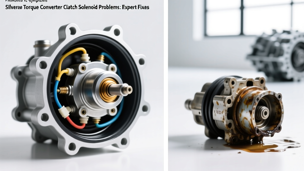
Torque converter clutch (TCC) shudder is often a fluid chemistry issue rather than a mechanical failure. The friction modifiers required for a CVT are vastly different from those in a traditional automatic.
- GM55 / 6L80 Applications: Require Dexron VI or Dexron ULV. These fluids contain specific friction modifiers designed for the aggressive apply-and-release of the TCC piston and the internal clutch packs. A worn-out fluid will lose its shear stability, leading to a 40-60 RPM TCC shudder under light throttle.
- CVT Applications: Require specialized CVTF (e.g., Honda HCF-2, GM ACDelco CVTF, or Nissan NS-3). CVTF has a lower viscosity (typically around 6.5 cSt at 100°C compared to 7.2+ cSt for Dexron) and contains high-friction modifiers designed to prevent the steel belt from slipping on the pulleys. If a technician accidentally tops off a CVT with standard ATF, the torque converter lockup clutch may engage properly, but the altered friction profile will cause the CVT belt to slip, mimicking a converter shudder.
Action: Always verify the exact fluid part number. For GM CVTs, ensure you are using ACDelco CVTF (Part # 10-9395 or updated equivalent), not standard Dexron.
Step 2: Perform the Simulated Slip Test (Avoid Traditional Stall Tests)
CRITICAL EXPERT WARNING: Never perform a traditional foot-brake stall test on a modern CVT. Holding the brakes while applying throttle in a CVT will instantly overwhelm the variator pulley clamping pressure, causing the steel belt to slip and permanently score the pulleys. This turns a minor torque converter issue into a $4,500 transmission replacement.
Instead, use your bidirectional scan tool to perform a Simulated TCC Slip Test.
- Connect your diagnostic tablet and access the Transmission Control Module (TCM) data stream.
- Monitor the
TCC_SLIP_RPM(Engine Speed minus Turbine Speed) andCVT_PRIMARY_PRESSUREPIDs. - Command the TCC solenoid OFF at a steady 45 MPH cruise.
- GM55 6L80 Expectation: Slip should immediately jump to 80-120 RPM and hold steady.
- CVT Expectation: Slip will increase, but the TCM will simultaneously ramp up primary and secondary line pressures to protect the belt. If the CVT belt slips, you will see erratic fluctuations in the primary pressure PID as the adaptive learning attempts to compensate.
Step 3: Analyze Harmonic Dampening and Lockup Strategies
If fluid is correct and simulated slip tests show normal hydraulic control, the issue is likely mechanical harmonic resonance. The GM55 torque converter utilizes a multi-stage turbine damper and often a CPA to absorb V8 firing pulses. When these springs fatigue, you will feel a rhythmic 15-20 Hz vibration through the chassis at exactly 1,200-1,500 RPM.
In contrast, CVT torque converters rely heavily on the flexplate and specialized damper springs to protect the belt. To diagnose this:
- Use an NVH (Noise, Vibration, and Harshness) app or chassis accelerometer.
- If the vibration frequency matches engine RPM divided by cylinder count (e.g., Engine Order 1 or 2), the torque converter damper or flexplate is failing.
- On Honda Earth Dreams CVTs, inspect the flexplate for cracked welds before condemning the torque converter, as the thin flexplate absorbs much of the launch shock.
Specification Comparison: GM55 vs. Modern CVT Converters
| Specification | GM55 Torque Converter (6L80 / 5.3L V8) | Modern CVT Torque Converter (e.g., Honda/Jatco) |
|---|---|---|
| Diameter | 300mm (Heavy Duty) | 220mm - 245mm (Compact/Low Inertia) |
| Hub / Spline Interface | 55mm Hub with standard splines | Specialized multi-spline or integrated flange |
| Launch Strategy | High-stall fluid coupling + aggressive TCC | Micro-slip TCC + high clamping pressure |
| Required Fluid Type | Dexron VI / Dexron ULV | CVTF (Low Viscosity, High Friction) |
| Stall Speed (Typical) | 1,800 - 2,200 RPM | 1,200 - 1,500 RPM (Belt protected) |
Source data adapted from Sonnax technical bulletins and ATRA transmission diagnostic guidelines.
Step 4: Removal, Seating, and Torque Specifications
If your diagnostics confirm internal torque converter failure (e.g., stripped stator splines, failed one-way clutch, or internal TCC piston seal blowout), proper removal and installation are paramount. The seating procedures differ significantly between the GM55 architecture and CVT platforms.
The Three-Point Seating Check
When installing a replacement GM55 torque converter onto a 6L80 or 8L90, you must feel three distinct "drops" or engagements:
- Turbine Hub Engagement: The converter splines slide over the transmission input shaft.
- Stator Support Engagement: The stator hub slots align with the stator support shaft.
- Oil Pump Engagement: The converter hub flats slot into the oil pump drive gear. Failure to achieve this third drop will result in immediate oil pump destruction upon startup.
CVT torque converters often integrate the oil pump drive directly into the converter cover or use a specialized chain-driven pump setup that does not require the traditional "third drop." Always consult the specific OEM service manual for the CVT model you are servicing.
Bellhousing and Flexplate Torque Specs
Improper torque on the flexplate or bellhousing bolts will alter the converter-to-flexplate clearance, leading to immediate TCC drag or pump cavitation.
- GM 5.3L (GM55 Setup): M12 Bellhousing bolts typically require 50 Nm + 90 degrees. Flexplate-to-converter nuts require 46 Nm. Ensure converter-to-flexplate clearance is between 3mm and 6mm.
- Typical CVT Setup (e.g., Honda/Toyota): M10 Bellhousing bolts usually torque to 44 Nm. Flexplate bolts are often 49 Nm plus a paint mark verification. CVT clearance is often much tighter, sometimes requiring precise shimming depending on the manufacturer.
Expert Tips for Long-Term Drivetrain Health
As transmission technology advances through 2026, the line between traditional automatics and CVTs continues to blur, with systems like Toyota’s Direct Shift-CVT utilizing both a physical launch gear and a torque converter. However, the fundamental rule remains: never treat a CVT like a traditional geared automatic.
When diagnosing a suspected GM55 torque converter in a truck application, you have the luxury of aggressive mechanical testing, high-stall fluid dynamics, and traditional stall speed verification. When diagnosing a CVT torque converter, your primary weapons are bidirectional scan tools, NVH analysis, and strict adherence to CVTF fluid chemistry. By respecting the unique engineering constraints of the CVT launch mechanism, you will avoid costly misdiagnoses and ensure the longevity of the variator assembly. For further reading on adaptive TCC learning procedures and valve body solenoid testing, refer to the latest technical resources from SAE International and OEM service portals.