The Physics of Friction Material Degradation
Diagnosing manual transmission drivability issues requires moving beyond subjective pedal feel and into quantifiable mechanical analysis. As of 2026, with the proliferation of high-torque platforms like the Tremec T56 Magnum F and the Honda K-Series turbo-swaps, understanding the exact lifecycle of friction materials is paramount. Clutch wear signs are rarely isolated to the friction disc alone; they often manifest as a cascading failure involving the pressure plate diaphragm, the flywheel friction surface, and the input shaft support.
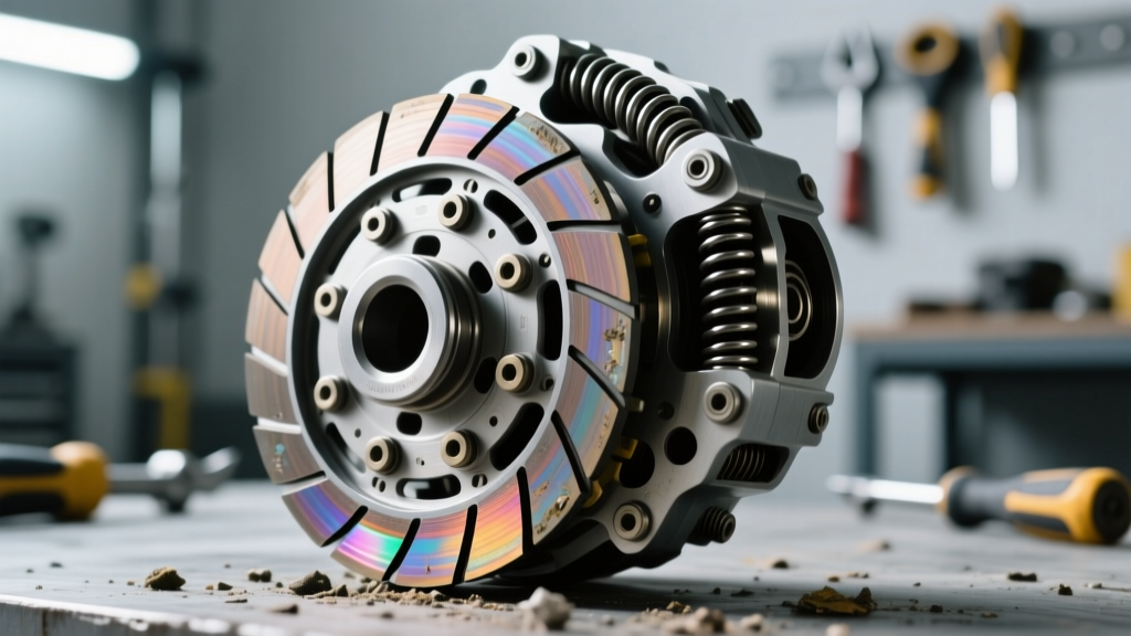
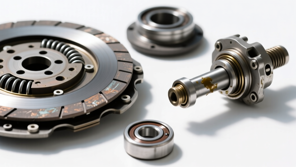
When organic or cerametallic friction material degrades, it loses its coefficient of friction (μ), leading to micro-slippage under peak torque loads. However, uneven wear patterns—such as inner or outer edge glazing—frequently point to input shaft misalignment. This misalignment is the primary catalyst that forces technicians to evaluate whether a simple disc swap will suffice, or if a comprehensive clutch pilot bearing replacement is required to restore concentricity between the engine crankshaft and the transmission input shaft.
Quantifiable Lifespan Indicators: Measuring the Wear
Visual inspection of the friction material is insufficient. True lifespan indicators rely on micrometer measurements of the disc facing thickness and the marcel spring (wave spring) deflection. According to Exedy's technical service bulletins, a clutch disc should be measured at the thickest point of the facing, accounting for any marcel spring compression.
| Platform / Application | New Disc Thickness | Service Limit (Replace) | Avg. Lifespan (Organic) |
|---|---|---|---|
| GM LS-Series (T56) | 3.80 mm (0.150") | 2.20 mm (0.086") | 60,000 - 80,000 miles |
| Honda K20/K24 (FWD) | 3.50 mm (0.138") | 2.00 mm (0.078") | 70,000 - 90,000 miles |
| Porsche G50 (964/993) | 4.10 mm (0.161") | 2.50 mm (0.098") | 50,000 - 65,000 miles |
| Subaru EJ25 (5MT Push) | 3.60 mm (0.141") | 2.10 mm (0.082") | 80,000 - 100,000 miles |
If the friction material is within 0.50 mm of the service limit, replacement is mandatory. Furthermore, if the marcel springs are flattened or fractured, the clutch will exhibit severe engagement chatter, a symptom that is frequently misdiagnosed as a warped flywheel.
Symptom Overlap: Clutch Chatter vs. Pilot Bearing Seizure
One of the most complex diagnostic challenges in the Clutch System Diagnostics category is isolating the source of low-frequency NVH (Noise, Vibration, and Harshness). Clutch chatter during take-off in first gear can stem from flywheel hot spots, oil contamination, or a failing pilot bearing.
Diagnostic Isolation Protocol
- The Engine-Off Test: With the engine off and transmission in neutral, depress the clutch pedal. If you feel mechanical binding or hear a dry scraping noise, the issue is likely in the pedal linkage, master cylinder, or release fork pivot ball.
- The Engine-On Neutral Test: Start the engine, leave the transmission in neutral, and depress the clutch. A high-pitched whine or growl that appears only when the pedal is pressed indicates a failing clutch release bearing (throw-out bearing), as noted in SKF's bearing diagnostic guides.
- The Gear Clash Test: With the engine running and the clutch pedal fully depressed, wait 3 seconds and attempt to shift into Reverse or 1st gear. If the gears grind or clash, the clutch is dragging. If the pedal feel is normal and the hydraulic system is bled, the input shaft is likely hanging up in a seized pilot bearing, preventing the disc from disengaging from the flywheel.
When the pilot bearing seizes or develops excessive radial play (typically beyond 0.003" of wobble), the transmission input shaft orbits off-center. This orbital wobble causes the clutch disc hub to bind on the splines and creates uneven friction material wear. Therefore, identifying these specific clutch wear signs inherently dictates that a clutch pilot bearing replacement must be performed during the teardown to prevent premature failure of the new friction assembly.
Technical Execution: Pilot Bearing Extraction and Installation
Executing a flawless clutch pilot bearing replacement requires precision tooling and strict adherence to thermal dynamics. The pilot bearing (or bronze bushing in older GM and Ford applications) is pressed into the rear flange of the crankshaft with high interference fit.
Extraction Methods
Never use a hammer and punch to knock out a pilot bearing; this risks spalling the crankshaft bore and sending brass shavings into the rear main seal. Instead, utilize a blind-hole bearing puller (e.g., OTC 4524 or Lisle 58100). For stubborn bronze bushings, the hydraulic extraction method is highly effective: pack the bore with heavy grease, insert a tight-fitting drift, and strike it with a brass hammer. The hydraulic pressure will pop the bushing out cleanly without damaging the crankshaft.
Thermal Installation and Depth Specifications
Expert Insight: Never hammer a new pilot bearing into the crankshaft. The shock loads can brinell the bearing races or deform the bushing ID, causing immediate input shaft binding. Always use thermal contraction and a proper installer tool.
Place the new bearing (such as an NTN 6203-2RS or Timken 202-FF) in a freezer at -10°F (-23°C) for 60 minutes, or use liquid nitrogen for a rapid shrink fit. Simultaneously, heat the crankshaft flange slightly with a heat gun to 150°F (65°C). The bearing will drop in with minimal pressure.
According to Tremec's manual transmission architecture guidelines, the pilot bearing depth is critical. The bearing must be installed flush to a maximum of 0.010" (0.25 mm) below the crankshaft flange surface. If installed too deep, the input shaft will bottom out inside the bearing, pushing the engine crankshaft forward and destroying the thrust bearing. If installed too proud, it will contact the clutch disc hub and cause severe vibration.
Flywheel Runout and Fastener Torque Matrix
A new clutch and a new pilot bearing will still fail prematurely if the flywheel mating surface is compromised. Always measure flywheel runout using a dial indicator mounted to the engine block. Maximum allowable runout for modern dual-mass and single-mass flywheels is 0.005" (0.12 mm). If runout exceeds this, the flywheel must be machined or replaced.
| Component | Application | Torque Spec / Procedure |
|---|---|---|
| Flywheel to Crankshaft | GM LS-Series (ARP / OEM) | 25 lb-ft + 50 degrees (Yield bolts) |
| Pressure Plate to Flywheel | M8 x 1.25 Bolts (Most platforms) | 18 - 22 lb-ft (Star pattern sequence) |
| Transmission to Engine Block | Tremec T56 / Magnum | 35 - 50 lb-ft (Depending on bellhousing) |
| Clutch Fork Pivot Ball | GM F-Body / GTO | 28 lb-ft (Apply high-temp threadlocker) |
2026 Cost and Labor Breakdown
When budgeting for a clutch system overhaul that includes a clutch pilot bearing replacement, parts and machine shop costs have shifted in 2026 due to supply chain adjustments in forged steel and friction composites. Below is a realistic cost matrix for a standard RWD performance application.
- Friction Kit (Exedy Stage 1 Organic or ACT Heavy Duty): $350 - $550
- Pilot Bearing / Bushing (OEM SKF / NTN): $18 - $45
- Clutch Release Bearing (Hydraulic CSC or Standard Collar): $65 - $180
- Flywheel Resurfacing (Machine Shop): $85 - $150 (Single Mass)
- Alignment Tool & Blind Hole Puller Rental: $45 - $75
- Total Parts & Machining (Excluding Labor): $563 - $1,000
By meticulously measuring clutch wear signs and addressing the root cause of input shaft misalignment through a proper pilot bearing replacement, you ensure the new friction assembly achieves its maximum engineered lifespan, eliminating drivetrain NVH and restoring precise shift quality.