The NVH Diagnostic Dilemma: Drivetrain vs. Accessory Clutches
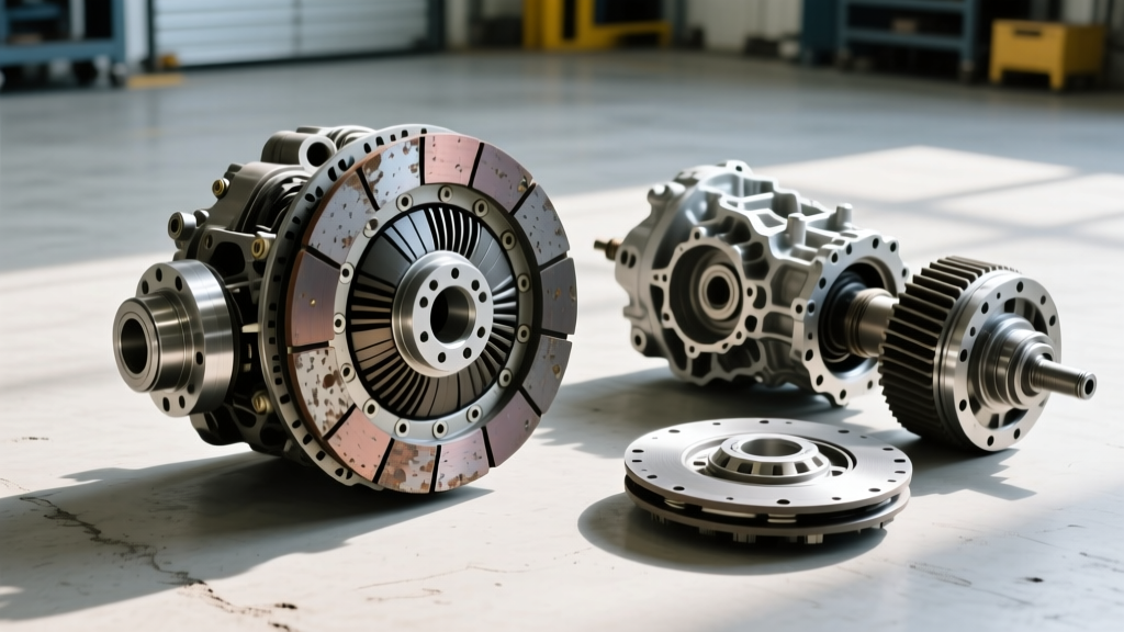
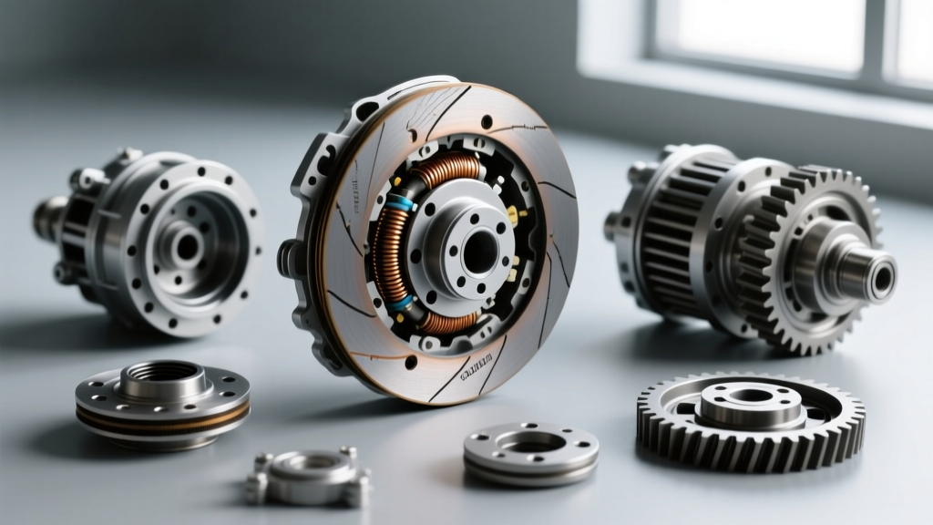
When a customer complains of 'clutch shudder,' 'chatter,' or 'RPM-dependent vibration,' novice technicians often immediately drop the transmission or split the bell housing. However, a comprehensive clutch system inspection checklist must account for the entire mechanical clutch ecosystem of the vehicle. This includes not only the manual friction disc or the automatic Torque Converter Clutch (TCC), but also the engine-driven accessory clutches—most notably, the viscous or electronic fan clutch.
A failing fan clutch bearing or seized viscous silicone fluid creates a harmonic vibration (typically between 40-60 Hz) that perfectly mimics a slipping TCC or a warped manual flywheel. In 2026, with the proliferation of 8-speed and 10-speed automatics utilizing aggressive micro-slip TCC strategies, isolating the source of Noise, Vibration, and Harshness (NVH) requires a systematic approach. This technical deep-dive provides a master checklist to diagnose drivetrain clutches and properly utilize a fan clutch tool to eliminate accessory-driven false positives.
Phase 1: Manual Drivetrain Clutch Inspection Checklist
For manual transmissions, clutch chatter and engagement issues are rarely isolated to the friction disc alone. The hydraulic actuation and release geometry must be measured before any teardown.
1. Pedal Geometry and Hydraulic Volume
- Freeplay Measurement: Verify pedal freeplay at the pad. Most OEM specifications (e.g., Honda, Mazda, Subaru) require 0.4 to 1.2 inches (10-30mm) of freeplay before the master cylinder pushrod engages. Zero freeplay causes premature throwout bearing failure and clutch slip under high load.
- Master/Slave Cylinder Bore Wear: Inspect the clutch slave cylinder travel. For a typical 5-speed or 6-speed manual, slave travel should be between 0.50' and 0.75'. If travel exceeds 0.85', the clutch fork pivot ball is likely worn, or the release bearing is collapsing.
- Hydraulic Fluid Condition: Check the DOT 3/DOT 4 reservoir. Dark, particulate-laden fluid indicates master cylinder seal degradation, leading to spongy engagement and incomplete disengagement (gear grind).
2. Bell Housing and Flywheel Runout
If the pedal and hydraulics check out, but chatter persists under load, measure flywheel runout. Using a dial indicator, acceptable runout is typically less than 0.004' (0.10mm). Excessive runout causes the clutch disc marcel springs to bottom out unevenly, resulting in aggressive low-speed chatter. When replacing components, always utilize a matched OEM kit (such as a LuK RepSet or Sachs OEM equivalent) to ensure the pressure plate diaphragm spring rate matches the transmission's input shaft damping requirements.
Phase 2: Automatic TCC (Torque Converter Clutch) Diagnostics
Modern automatic transmissions rely on the TCC to lock the engine to the transmission input shaft, eliminating parasitic fluid losses. However, TCC shudder is a pervasive issue in units like the GM 6L80, 8L90, and the ZF 8HP series.
Isolating TCC Shudder
TCC shudder usually occurs during light-throttle acceleration between 35-55 MPH in 4th, 5th, or 6th gear. The TCC is commanded to a 'controlled slip' state (typically 20-40 RPM slip) to dampen engine torsional vibrations. If the friction material inside the converter degrades, or the TCC regulator valve in the valve body wears, the slip oscillates, causing a 40-50 Hz vibration.
Expert Diagnostic Tip: Use a high-end bi-directional scan tool to command the TCC solenoid to 0% duty cycle (fully unlocked) while driving at the speed where the shudder occurs. If the vibration instantly disappears, the issue is isolated to the TCC apply circuit, the valve body, or the converter itself. For deeper valve body diagnostics, refer to the Sonnax TCC Shudder Diagnostic Guide.
If the vibration persists even with the TCC fully unlocked, you must look outside the transmission to the engine's accessory drive—specifically, the fan clutch.
Phase 3: Accessory Clutch & Fan Clutch Tool Application
The engine cooling fan clutch is a fluid-coupled or electronically controlled clutch mounted to the water pump shaft. When the internal viscous fluid shears and loses its silicone properties, or when the internal bi-metallic strip fails, the fan clutch can bind or wobble. This wobble translates directly through the water pump bearings into the engine block, creating a vibration that feels exactly like a failing torque converter.
Using the Fan Clutch Tool for Removal and Inspection
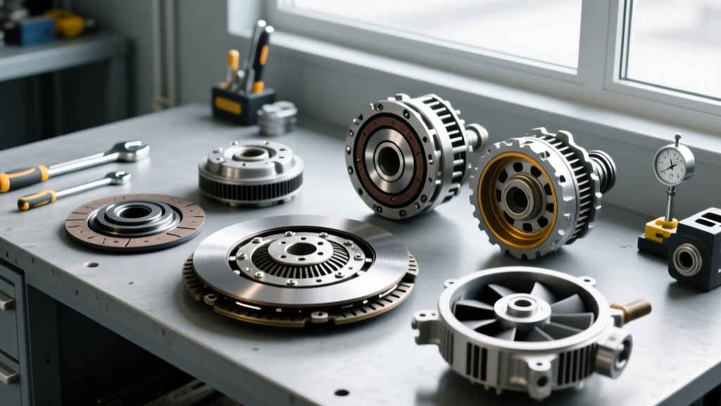
Diagnosing a viscous fan clutch requires physical removal to test rotational resistance and inspect the bearing. To do this, a specialized fan clutch tool (such as the Lisle 39260 or OTC 4571 Fan Clutch Wrench set) is mandatory. These tools feature thin-profile wrenches (commonly 36mm, 47mm, or 1-1/4') designed to fit the narrow gap between the fan clutch nut and the water pump pulley.
- Identify Thread Direction: This is critical. Most standard-rotation engines (like the GM LS series) use standard right-hand threads. However, many Ford engines (like the 5.0 Coyote) and specific Chrysler applications use reverse (left-hand) threads because the fan spins counter-clockwise to prevent the nut from backing off during operation.
- Secure the Pulley: Use the accompanying water pump pulley holding tool or a specialized strap wrench to prevent the serpentine belt and pulley from turning while applying torque to the fan clutch nut.
- Extract and Test: Once removed, hold the fan clutch horizontally and spin it. A healthy viscous clutch will offer smooth, heavy resistance and stop spinning within 1 to 1.5 revolutions. If it spins freely like a standard bearing, the viscous fluid has leaked or sheared, necessitating replacement.
For a detailed breakdown of tool profiles and thread applications, consult the Lisle Fan Clutch Wrench application data.
Diagnostic Matrix: Viscous, Electronic, and Drivetrain Clutches
| Clutch System Type | Primary Failure Mode | NVH Symptom Profile | Diagnostic Tool / Method |
|---|---|---|---|
| Manual Friction Clutch | Marcel spring fatigue, warped flywheel, oil contamination | Low-speed (1st/2nd gear) chatter upon pedal release; pedal pulsation. | Dial indicator (flywheel runout), hydraulic slave travel measurement. |
| Automatic TCC | Converter friction wear, TCC regulator valve bore wear | 40-50 Hz shudder at 35-55 MPH under light throttle; RPM fluctuation on scan tool. | Bi-directional scan tool (command TCC unlock), Sonnax ZIP kit inspection. |
| Viscous Fan Clutch | Silicone fluid shear, bi-metallic strip failure, bearing seizure | High-RPM harmonic vibration; 'roaring' noise; mimics TCC shudder but independent of gear. | Fan clutch tool (36mm/47mm), horizontal spin test, thermal gun. |
| Electronic Fan Clutch | PWM solenoid failure, internal wiring harness chafing | Intermittent vibration; cooling system overheating; Check Engine Light (e.g., P0480). | Oscilloscope (PWM signal verification), scan tool active command. |
Torque Specifications, Fluids, and Replacement Costs
Proper reassembly is just as critical as diagnosis. Over-torquing a fan clutch nut can crack the water pump snout, while under-torquing a manual clutch pressure plate will result in immediate catastrophic slip. Below is a reference matrix for common 2026-era service procedures.
Drivetrain Clutch Torque & Fluid Specs
- GM 6L80 / 8L90 TCC Service: If performing a valve body and TCC solenoid replacement, use Dexron ULV or Dexron VI depending on the exact year. Valve body torque specs are incredibly low, typically 8-10 Nm (71-89 lb-in). Over-torquing warps the valve body casting, causing immediate cross-leaks and TCC apply failures.
- ZF 8HP Series: Requires ZF LifeguardFluid 8. The mechatronic sleeve and TCC PWM solenoid are common failure points for shudder. Mechatronic adapter bolts must be torqued to exactly 10 Nm to prevent sleeve cracking.
- Manual Pressure Plate: Most M8x1.25 pressure plate bolts require 25-35 Nm (18-25 lb-ft) in a star pattern. Always use the alignment tool included in the LuK or Sachs RepSet to ensure the disc is perfectly centered, preventing input shaft binding.
Estimated Repair Costs (Parts & Labor)
- Fan Clutch Replacement: $250 - $450. (Includes OEM clutch, serpentine belt, and 0.8 hours labor. Specialty fan clutch tool ownership is required for DIY).
- TCC Solenoid / Valve Body Service: $600 - $1,200. (Requires pan drop, fluid exchange, and solenoid reflash/relearn via scan tool).
- Full Manual Clutch Replacement (FWD/RWD): $1,400 - $2,800. (Includes OEM clutch kit, flywheel resurfacing/replacement, master/slave cylinder bleed, and 5-8 hours of labor).
Final Verification: The Road Test Protocol
After completing the clutch system inspection checklist and executing the necessary repairs, a standardized road test is mandatory. For automatics, monitor the TCC slip RPM via the scan tool while maintaining a steady 50 MPH on a flat grade. Slip should hold steady at the commanded 20-40 RPM without oscillating. For manual transmissions, verify that the clutch engages smoothly between 1,200 and 1,500 RPM with zero pedal pulsation. Finally, rev the engine to 3,500 RPM in neutral to ensure the newly installed or inspected fan clutch does not introduce high-RPM harmonic noise, confirming that the accessory drive is fully decoupled from the drivetrain NVH profile.
For further reading on advanced automatic transmission diagnostics and valve body wear patterns, the Automatic Transmission Service Group (ATSG) remains the industry standard for technical bulletins and teardown procedures.