The Kinematics of Manual Transmission Release Systems
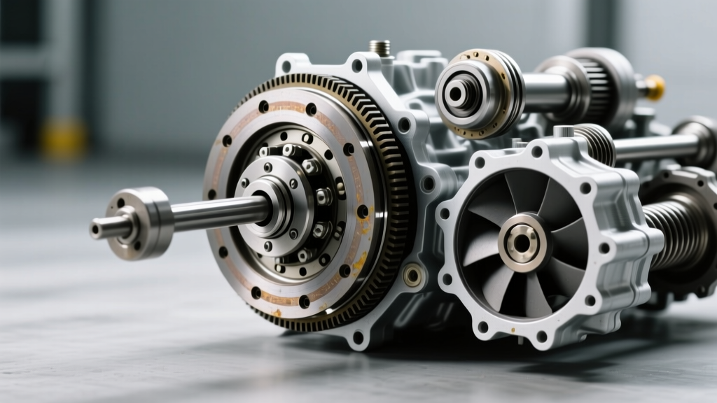
Diagnosing manual transmission health requires translating tactile feedback at the driver’s footwell into mechanical realities inside the bellhousing. Unlike automatic transmissions, where planetary gearset wear is hidden behind valve body hydraulics and torque converters, a manual clutch assembly provides direct, measurable feedback regarding its remaining lifespan. The most critical, yet frequently misunderstood, diagnostic metric is pedal free travel. Understanding the kinematics of the release system—from the master cylinder pushrod to the throwout bearing (TOB) riding the diaphragm spring fingers—is essential for accurate clutch system diagnostics.
Modern hydraulic clutch systems typically utilize a 5/8-inch or 3/4-inch bore master cylinder paired with a concentric slave cylinder (CSC) or an external slave acting on a release fork. The system is designed with a specific volume of displacement required to fully actuate the pressure plate. However, before that displacement translates into clutch disengagement, a specific gap must be closed. This gap is the physical clearance between the face of the TOB and the tips of the pressure plate’s diaphragm spring fingers.
Why the Clutch Free Pedal Should Be Able to Move
When evaluating clutch wear signs, the fundamental rule of mechanical sympathy dictates that the clutch free pedal should be able to move at least 1.0 to 1.5 inches (25mm to 38mm) at the pedal pad before any hydraulic resistance is felt. This “dead zone” or free play is not a manufacturing defect; it is a vital engineering clearance.
Engineering Note: If the clutch free pedal does not move freely before hitting hydraulic resistance, the throwout bearing is pre-loaded against the spinning diaphragm spring fingers. This constant friction generates immense localized heat, leading to premature TOB failure, glazing of the friction disc, and eventual pressure plate finger fatigue.
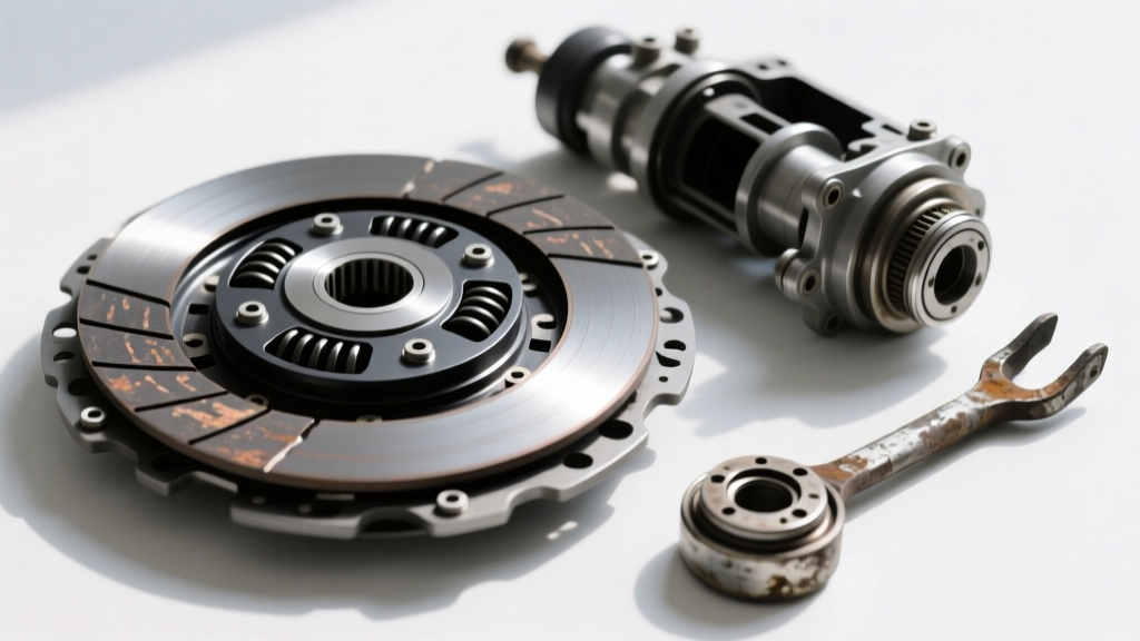
As the clutch friction disc wears, its overall thickness decreases. A typical organic friction disc measures approximately 9.0mm thick when new. As it wears down toward the 4.0mm replacement threshold, the pressure plate moves closer to the flywheel to maintain clamping force. Because the diaphragm spring pivots on a fulcrum ring, the inward movement of the pressure plate causes the spring fingers to pivot outward, toward the transmission. This outward pivot inherently consumes the clearance between the fingers and the TOB. If the hydraulic system lacks a self-adjusting mechanism, or if a cable clutch is not manually adjusted, the free pedal travel will progressively shrink to zero.
Quantitative Wear Indicators: Mapping Pedal Geometry
By measuring the engagement point (the bite point) relative to the floorboard, and the free play at the top of the pedal stroke, technicians can accurately estimate the remaining lifespan of the friction material. The following diagnostic matrix outlines the correlation between pedal geometry and internal clutch wear.
| Pedal Free Play | Engagement Point (from floor) | Diagnostic Status | Required Action |
|---|---|---|---|
| 1.25" - 1.50" (32-38mm) | Low (1-2 inches off floor) | New / Excellent Condition | Verify hydraulic fluid level; baseline measurement. |
| 0.50" - 1.00" (12-25mm) | Mid-Stroke (3-5 inches) | Normal Wear (50-70% Life) | Monitor; check for slave cylinder weeping. |
| 0.00" (Zero Free Play) | High (Near top of stroke) | Critical Wear / TOB Pre-load | Immediate adjustment or replacement; high risk of slip. |
| Excessive (> 2.00") | Failing to disengage fully | Hydraulic Bypass / Air in Line | Bleed system; inspect master cylinder internal seals. |
The Self-Adjusting Clutch (SAC) Anomaly
When diagnosing modern European and late-model Asian vehicles, technicians must account for the Self-Adjusting Clutch (SAC) technology pioneered by Schaeffler (LuK). SAC pressure plates feature an internal ramp ring and adjustment mechanism that automatically rotates to compensate for friction disc wear. This maintains a constant clamping load and, crucially, keeps the diaphragm spring fingers at a fixed depth relative to the TOB.
SAC Diagnostic Edge Cases
- The False Sense of Security: Because SAC systems maintain constant pedal free play and engagement height, the pedal will feel “new” even when the friction disc is worn down to the rivets.
- The Sudden Failure Mode: Once the internal adjustment ring reaches its maximum mechanical travel, the SAC mechanism can no longer compensate. The pedal will suddenly drop, or the clutch will begin to slip aggressively without prior warning signs.
- Installation Protocol: Replacing a SAC requires a specialized alignment tool (e.g., LuK 400 0055 00) to pre-load the adjustment ring. Failure to use this tool results in immediate engagement issues upon installation.
Hydraulic Degradation vs. Mechanical Wear
Not all changes in pedal feel are caused by friction material wear. The hydraulic actuation system is highly susceptible to environmental and thermal degradation, which can mimic mechanical clutch failure.
Most OEM systems utilize DOT 3 or DOT 4 glycol-based brake fluid. This fluid is highly hygroscopic, absorbing up to 3% water by volume over a two-year period. As water content increases, the fluid’s boiling point drops from a dry 446°F (DOT 4) to a wet 311°F. In high-performance or heavy-duty applications, heat transfer from the bellhousing to the concentric slave cylinder can cause localized fluid boiling, resulting in a spongy pedal that fails to disengage the clutch.
Furthermore, internal bypassing of the clutch master cylinder is a notorious failure point on platforms like the Honda K-Series and GM T56-equipped vehicles. When the internal rubber cup seals wear against the scored aluminum bore of the master cylinder, fluid bypasses the piston during slow pedal actuation. This results in a pedal that feels firm when pumped rapidly, but slowly sinks to the floor when held down at a stoplight, eventually causing the vehicle to creep forward in gear.
Replacement Thresholds and 2026 Component Specifications
When clutch wear signs dictate replacement, precision in reassembly is non-negotiable. The following specifications reflect standard OEM and high-performance replacement protocols for common RWD V8 applications (e.g., GM LS-series with TREMEC T56 Magnum transmissions).
Critical Assembly Torque Specifications
- Flywheel to Crankshaft (ARP 200-2802 12mm Bolts): 85 lb-ft + 80 degrees of torque angle. Must use new TTY (Torque-to-Yield) bolts or ARP moly-lube with specific tension ratings.
- Pressure Plate to Flywheel (M8 x 1.25 Bolts): 26 lb-ft (35 Nm), tightened in a strict star pattern to prevent diaphragm spring distortion.
- Bellhousing to Engine Block (M12 Bolts): 37 lb-ft (50 Nm). Misalignment here causes input shaft binding and premature pilot bearing failure.
- Clutch Fork Pivot Ball: Inspect for asymmetric wear. Replace with a hardened steel adjustable pivot (e.g., McLeod or Tick Performance) to restore optimal TOB geometry.
Cost Baselines and Part Selection
As of 2026, a premium OEM-equivalent clutch kit (such as an Exedy OEM Replacement or LuK RepSet, including disc, pressure plate, TOB, and alignment tool) ranges from $280 to $450. High-capacity organic or cerametallic kits (e.g., Exedy Stage 1) push this to $600–$850. Labor for a standard RWD transmission drop averages 6.0 to 8.5 hours, translating to $900–$1,500 in shop time. Cutting corners on the slave cylinder or flywheel resurfacing during this service interval is a false economy that guarantees a repeat failure.
Conclusion: Respecting the Free Play
The manual transmission clutch is a consumable wear item, but its degradation is entirely predictable if monitored correctly. By understanding that the clutch free pedal should be able to move to protect the release bearing and ensure full clamping force, drivers and technicians can intervene before catastrophic slip or drivetrain damage occurs. Regular measurement of pedal free play, combined with an understanding of SAC technology and hydraulic fluid dynamics, transforms clutch diagnostics from a guessing game into an exact science.