The Semantic Diagnostic Trap: Drivetrain vs. Accessory Clutches
In the 2026 automotive service landscape, manual transmissions have largely transitioned from everyday commuter staples to specialized performance and enthusiast platforms. Consequently, many newer technicians lack the deep mechanical intuition required to diagnose manual clutch linkage failures. This knowledge gap frequently leads to severe diagnostic misdirection, particularly when customers use the word 'clutch' to describe entirely different vehicle systems.
Consider a highly deceptive scenario: a customer books an appointment complaining about an air conditioning compressor clutch not engaging, especially when the vehicle is idling in gear or under heavy throttle. The immediate instinct for a novice technician is to pull out a multimeter and chase electrical gremlins—testing the A/C relay, the refrigerant pressure transducer, or the PCM’s load-shedding logic. However, a failing manual transmission clutch fork and pivot ball assembly can be the hidden mechanical culprit triggering this exact symptom.
How does a mechanical drivetrain component cause an electrical accessory failure? When a clutch fork pivot ball is severely worn or the fork itself is binding, the mechanical clutch fails to fully disengage. This causes the engine to lug, shudder, and nearly stall when the vehicle is shifted into gear at a stop. Modern Powertrain Control Modules (PCMs) monitor engine RPM and parasitic load continuously. Detecting a severe RPM drop and excessive drivetrain drag, the PCM will actively interrupt the A/C compressor clutch relay to shed parasitic load and prevent the engine from stalling. Thus, the primary symptom of an SAE documented load-shedding event—an air conditioning compressor clutch not engaging—is actually a secondary failsafe response to a mechanical clutch fork binding issue. Recognizing this cross-system interaction is the hallmark of an expert drivetrain diagnostician.
Anatomy of Clutch Fork and Pivot Ball Failure
To understand why this failure occurs, we must examine the mechanical leverage of the clutch release system. Whether you are working on a classic GM Muncie 4-speed, a Ford Toploader, or a modern Tremec T-56 Magnum, the fundamental geometry remains identical. The clutch fork acts as a lever. The pivot ball (or pivot stud) serves as the fulcrum. The hydraulic throwout bearing or mechanical release collar acts as the load.
When the driver depresses the clutch pedal, hydraulic pressure pushes the slave cylinder, which in turn pushes the clutch fork. The fork pivots on the ball, forcing the throwout bearing against the pressure plate diaphragm fingers. Over tens of thousands of cycles, the friction between the clutch fork's internal contact pads and the spherical pivot ball generates immense wear.
Common Failure Modes in Manual Transmissions
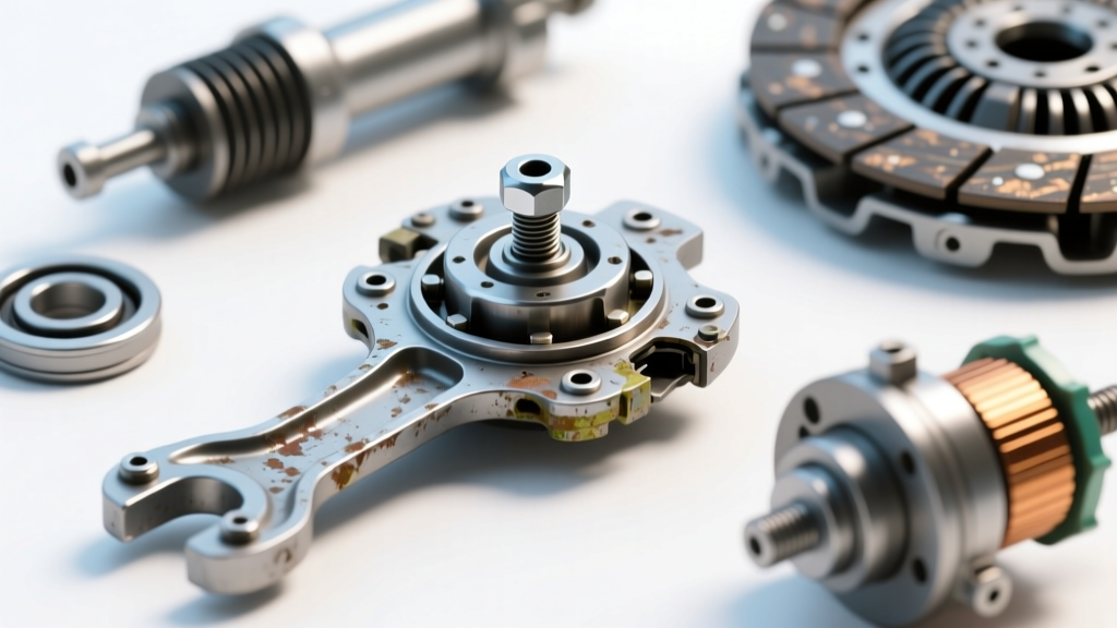
- Asymmetrical Pad Wear: The clutch fork rides on two small contact pads or a cupped surface. If the bellhousing is misaligned, the fork is pushed at an angle, wearing one pad down to the bare metal while the other remains intact.
- Pivot Ball Grooving: The spherical pivot ball can develop deep grooves or flat spots. This alters the fulcrum geometry, effectively shortening the throw of the fork and resulting in incomplete clutch disengagement (gear grinding).
- Pivot Stud Stretch or Loosening: The pivot stud threads into the engine block or bellhousing. Under high-RPM shifting, the shock load can cause the stud to back out if proper threadlocker was not applied, leading to a sudden 'dead pedal' feel.
- Z-Bar and Linkage Bind: In older mechanical linkage setups, the Z-bar pivot points can seize due to lack of lubrication, mimicking the symptoms of a worn internal fork.
Precision Measurement and Torque Specifications
Diagnosing clutch fork and pivot issues requires the transmission to be removed. Once the bellhousing is exposed, visual inspection is not enough; precision measurement is mandatory. Below is a reference chart for standard OEM and performance clutch fork components, including critical wear limits and torque specifications.
| Component | OEM / Performance Part Example | Maximum Wear Limit | Torque Specification |
|---|---|---|---|
| Pivot Ball Stud | Dorman 14580 (Standard GM) | 0.015' thread stretch / galling | 30 lb-ft (w/ Loctite 243) |
| Clutch Fork Pads | McLeod 16950 (Steel Fork) | 0.030' pad material loss | N/A (Inspection Only) |
| Adjustable Pivot Ball | McLeod 16950 (Bronze Sphere) | 0.010' sphere diameter loss | 15 lb-ft (Locknut against stud) |
| Fork Pivot Pin (Internal) | Tremec T-56 Magnum Pin | 0.005' lateral play | 12 lb-ft (Retainer Bolt) |
Note: Always consult the specific factory service manual for your application, as torque specs can vary between aluminum and cast-iron bellhousings.
Advanced Bellhousing Geometry and Runout
You cannot properly diagnose clutch fork wear without addressing bellhousing runout. This is a step that 90% of general repair shops skip, leading to recurring clutch fork failures and premature throwout bearing destruction. The pivot ball is threaded into the bellhousing or the engine block. The transmission input shaft passes through the center of the bellhousing. If the bellhousing is not perfectly concentric to the engine crankshaft, the pivot ball and the input shaft are operating on two different centerlines.
When this misalignment occurs, the clutch fork is forced to twist laterally as it pushes the throwout bearing forward. This twisting action binds the fork on the pivot ball, creating immense friction and rapid, asymmetrical wear on the fork's contact pads.
How to Measure Bellhousing Runout
- Mount a magnetic base dial indicator to the engine block or crankshaft flange.
- Position the indicator needle against the inner bore of the bellhousing where the transmission front bearing retainer seats.
- Rotate the crankshaft a full 360 degrees by hand.
- Record the Total Indicator Reading (TIR). The maximum allowable runout for most modern manual transmissions (including Tremec and BorgWarner units) is 0.005 inches.
- If runout exceeds 0.005', you must install offset dowel pins to realign the bellhousing before installing a new clutch fork and pivot ball.
2026 Best Practices for Replacement and Upgrades
When replacing a worn clutch fork and pivot assembly, the goal is to restore exact factory geometry while upgrading materials to withstand modern high-torque applications. In 2026, with aftermarket performance clutches generating upwards of 3,500 lbs of clamp load, standard stamped-steel forks and mild-steel pivot balls are often insufficient.
Material Upgrades
- Bronze Pivot Balls: Upgrading from a hardened steel pivot ball to a phosphor-bronze pivot ball (such as those offered by McLeod Racing) drastically reduces friction. Bronze is self-lubricating and sacrificial, meaning it will wear slightly to protect the more expensive clutch fork and throwout bearing carrier.
- Adjustable Pivot Studs: Aftermarket clutch assemblies often alter the distance between the pressure plate diaphragm fingers and the bellhousing mounting face. An adjustable pivot stud allows you to dial in the exact fulcrum point, ensuring the clutch fork maintains the correct 1/8-inch to 1/4-inch free-play at the throwout bearing.
- Forged Aluminum Forks: For high-RPM track applications, billet or forged aluminum clutch forks reduce reciprocating mass, allowing for faster, crisper shifts without the harmonic flex inherent in stamped steel.
Cost and Labor Expectations
Because accessing the clutch fork requires dropping the transmission, the parts cost is negligible compared to the labor. A standard OEM pivot stud and fork assembly will cost between $45 and $120. High-end adjustable bronze pivot kits range from $85 to $160. However, the labor to remove the transmission, exhaust, and driveshaft typically ranges from $600 to $1,400 depending on the vehicle platform and whether it is a solid-axle or independent rear suspension setup.
Conclusion: Holistic Drivetrain Diagnostics
Mastering clutch system diagnostics requires looking beyond the immediate mechanical symptoms and understanding how the drivetrain interacts with the vehicle's broader electronic and accessory networks. The next time you are faced with a confusing customer complaint—whether it is a grinding gear, a dead pedal, or even an apparent electrical fault like an air conditioning compressor clutch not engaging—remember to trace the mechanical leverage from the pedal to the pivot ball. By utilizing precision measurement tools, adhering to strict bellhousing runout tolerances, and selecting the correct metallurgy for the application, you can permanently resolve clutch engagement issues and restore the vehicle to peak performance.