Understanding Clutch Drag and Release Problems
Clutch drag occurs when the friction disc fails to fully disengage from the flywheel or pressure plate while the clutch pedal is fully depressed. This results in gear clash, difficulty entering first or reverse gear from a stop, RPM hang, and excessive synchronizer wear inside the transmission. In modern manual vehicles equipped with hydraulic concentric slave cylinders (CSC) and dual-mass flywheels (DMF), diagnosing clutch drag and release problems requires a systematic approach that separates hydraulic deficiencies from mechanical wear and parasitic engine loads.
Before dropping the transmission and inspecting the bellhousing, a senior diagnostic technician must isolate external variables. Misdiagnosing a seized accessory drive component as a failed clutch pack is a common and expensive mistake. This guide provides a step-by-step framework for isolating, measuring, and repairing manual transmission clutch drag.
Phase 1: Ruling Out Parasitic Accessory Drag
When an engine struggles to return to idle or the transmission feels bound up when shifting, the issue is not always inside the bellhousing. A failing A/C compressor clutch or a seized pulley bearing places a massive parasitic load on the engine, mimicking the exact symptoms of drivetrain clutch drag.
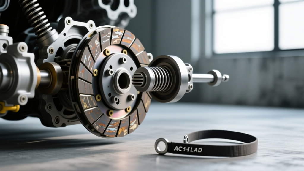
During A/C compressor service, mechanics often use an ac clutch tie strap or a specialized strap wrench to bind the pulley to the hub, holding it stationary to break the center bolt loose. This same isolation logic applies to drivetrain diagnostics. To rule out the A/C compressor:
- The Tie-Strap Isolation Test: Thread a heavy-duty nylon tie strap through the A/C clutch pulley vents and secure it to a rigid mounting point on the compressor body. This physically prevents the pulley from spinning independently of the hub.
- Belt Removal Method: Alternatively, remove the serpentine belt entirely. Start the engine, depress the clutch pedal, and attempt to shift into first and reverse.
If the gear clash disappears and the transmission shifts smoothly without the accessory belt, your clutch system is healthy, and the A/C compressor or tensioner is the culprit. If the drag persists, proceed to the hydraulic and mechanical diagnostics below.
Phase 2: Hydraulic Release System Diagnostics
Modern manual transmissions rely on hydraulic release systems to multiply pedal force. A failure to achieve adequate stroke at the throw-out bearing is the leading cause of clutch drag. According to Schaeffler LuK Aftermarket, over 70% of premature clutch failures and release issues stem from improper hydraulic bleeding or degraded fluid.
Concentric Slave Cylinder (CSC) Bleeding Protocols
Vehicles utilizing an internal CSC (such as the GM Tremec TR-6060 or Ford MT-82 applications) feature a built-in bleed orifice that traps air if manual gravity bleeding is attempted. To properly bleed a CSC system:
- Fluid Selection: Use only OEM-specified DOT 4 or DOT 5.1 brake fluid. DOT 4 fluid has a dry boiling point of 446°F (230°C), which is critical as the CSC sits directly inside the hot bellhousing.
- Pressure Bleeding: Connect a pressure bleeder to the master cylinder reservoir at 15-20 PSI. Never exceed 25 PSI, as this can rupture the internal CSC seals.
- Pedal Cycling: Slowly depress the pedal to the floor, hold for 3 seconds, and release. Repeat 15-20 times. The slow release allows the internal return spring to push micro-bubbles back up through the compensating port into the reservoir.
- Stroke Verification: Measure the slave cylinder pushrod travel. For most FTE and LuK CSC units, minimum required travel to fully disengage a 240mm clutch is between 11.5mm and 13.0mm.
Phase 3: Mechanical Linkage and Fork Geometry
If the hydraulic system is generating adequate pressure and travel, the next suspect is mechanical wear within the bellhousing. Clutch drag frequently occurs when the clutch fork geometry is altered by worn pivot points, reducing the effective throw of the release bearing.
Pivot Ball and Fork Pad Wear
In external slave cylinder setups (like the classic Tremec T56 Magnum), the clutch fork pivots on a hardened steel ball stud. Over 80,000 miles, the spherical socket in the cast-iron or stamped-steel fork wears down.
- Inspection: Remove the fork and inspect the pivot contact patch. If a wear groove deeper than 0.015 inches is present, the fork must be replaced.
- Pivot Ball Torque: When reinstalling the pivot ball into the bellhousing boss, apply high-temperature moly grease and torque to 20-25 lb-ft (verify with specific Tremec Engineering service manuals). Over-torquing can strip the aluminum bellhousing threads, altering the pivot height.
- Fork Finger Wear: Check the fork fingers that contact the throw-out bearing sleeve. Excessive wear here introduces dead-band into the pedal travel, meaning the hydraulic cylinder exhausts its stroke before the diaphragm spring is fully depressed.
Phase 4: Flywheel Step Height and Clutch Pack Tolerances
Perhaps the most misunderstood cause of clutch drag is improper flywheel step height. The 'step' is the distance between the friction surface of the flywheel and the mounting surface of the pressure plate. If a flywheel is resurfaced incorrectly, the pressure plate is pulled closer to the engine block, reducing the clamping load and altering the diaphragm spring angle, which can cause the clutch to drag even when fully depressed.
Measuring Step Height
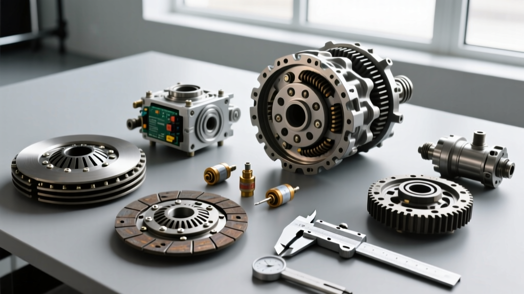
As outlined in comprehensive AA1Car Clutch Diagnostics guides, step height must be verified with a straightedge and dial caliper before installing the clutch assembly.
- GM LS Applications (e.g., LS3, LS7): Standard step height is typically 0.030 to 0.050 inches. If the step is worn down to 0.000 (flat), the pressure plate cannot clamp properly, and release geometry is compromised.
- Ford Modular V8 (e.g., 4.6L, 5.0L Coyote): Step height usually ranges from 0.015 to 0.035 inches depending on the specific clutch manufacturer (e.g., McLeod vs. Exedy).
If the step height is out of spec, the flywheel must be machined with a stepped cut or replaced. Shimming the pressure plate with washers is a dangerous practice that leads to uneven clamping, warped friction discs, and catastrophic release failure.
Pilot Bearing Clearance
A binding pilot bearing will keep the transmission input shaft spinning even when the clutch disc is released. This causes severe gear clash that feels exactly like clutch drag. Always use a dedicated pilot bearing puller for removal. When installing a new sintered bronze bushing or needle bearing, ensure the clearance between the bearing and the transmission input shaft tip is between 0.005 and 0.010 inches. A tight pilot bearing will gall the input shaft and cause permanent drag.
Diagnostic Reference Table: Clutch Drag Failure Modes
| Component | Failure Mode | Diagnostic Measurement / Spec | Corrective Action |
|---|---|---|---|
| Hydraulic CSC | Internal bypass / Air entrapment | Pushrod travel < 11.5mm | Pressure bleed at 20 PSI; replace CSC if seals bypass |
| Clutch Fork | Pivot socket wear | Wear groove > 0.015 inches | Replace fork; inspect pivot ball for galling |
| Flywheel | Incorrect step height | Step < 0.030 inches (GM LS) | Machine flywheel to restore step or replace DMF |
| Pilot Bearing | Seized / Binding on input shaft | Clearance < 0.005 inches | Extract bearing; ream bushing to 0.008 inch clearance |
| Friction Disc | Warped marcel spring / splines binding | Disc runout > 0.020 inches | Replace clutch disc; lubricate splines with minimal high-temp grease |
Summary
Resolving clutch drag and release problems requires looking beyond the pedal. By first utilizing isolation techniques—much like using an ac clutch tie strap to rule out accessory drag—you prevent unnecessary transmission removal. From there, verifying hydraulic stroke, inspecting bellhousing pivot geometry, and strictly adhering to flywheel step-height tolerances will ensure a crisp, drag-free clutch engagement for the life of the drivetrain.