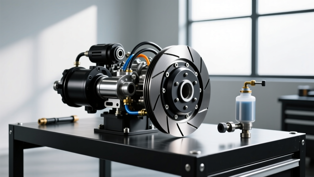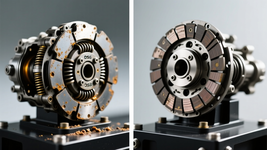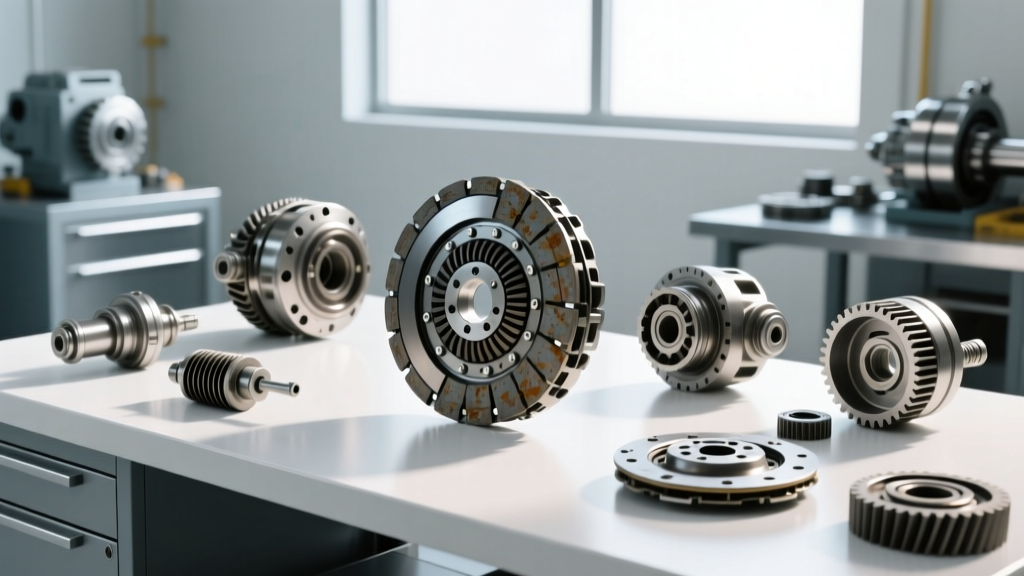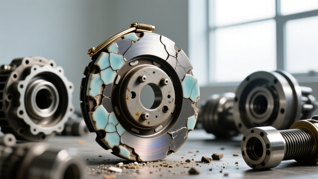
When upgrading a manual transmission drivetrain for high-horsepower applications, sintered ceramic friction materials are often the default choice. (Note: In enthusiast forums and search queries, you may occasionally encounter the term 'caremal clutch'; this is a common typographical error for ceramic clutch. The diagnostic principles and metallurgical data below apply strictly to sintered ceramic friction materials.) Unlike organic or Kevlar compounds, ceramic discs utilize a sintered iron and ceramic metallic blend that thrives under extreme thermal loads. However, this aggressive friction profile introduces unique wear patterns, pedal feel changes, and failure modes that require precise diagnostic techniques.
The Material Science of Sintered Ceramic Friction
To accurately diagnose wear, one must first understand the operating parameters of the friction material. Ceramic clutch facings typically exhibit a coefficient of friction (Mu) between 0.45 and 0.55, significantly higher than the 0.30 to 0.38 range of standard organic discs. This high Mu allows a single-disc ceramic setup to hold 700 to 1,000+ lb-ft of torque at the crankshaft. However, the abrasive nature of sintered ceramic means it acts almost like a lapping compound against the flywheel and pressure plate mating surfaces. Wear is not just measured in disc thickness, but in the degradation of the entire clamping assembly.
The 4-Stage Diagnostic Protocol for Ceramic Wear
Diagnosing a ceramic clutch requires moving beyond the simplistic 'slip test.' Because ceramic materials do not fade gradually like organic compounds—they tend to hold firmly until they reach a critical failure threshold—technicians must monitor specific lifespan indicators.
Stage 1: Bite Point Migration and Hydraulic Compensation
The earliest indicator of ceramic disc wear is the migration of the engagement point (bite point). As the ceramic facing wears down (often losing 1.5mm to 2.5mm over its lifespan), the pressure plate diaphragm fingers move closer to the release bearing. In vehicles equipped with self-adjusting hydraulic slave cylinders (such as the Tremec T56 Magnum or MT-82 applications), the hydraulic system compensates for this wear. However, you can measure this compensation by checking the clutch master cylinder pushrod free-play. If the free-play drops below the OEM specification of 0.5mm to 1.0mm, the system is at risk of clutch drag, as the release bearing is being pre-loaded against the diaphragm springs, preventing full clamping force.
Stage 2: Load-Based Slippage (The 4th Gear WOT Test)
Ceramic clutches rarely slip during light-throttle city driving. To diagnose mid-life wear, a load-based test is required. Safely perform a Wide Open Throttle (WOT) pull in 4th gear starting at 2,500 RPM. Monitor the relationship between engine RPM and vehicle speed (MPH). If the RPM needle climbs disproportionately faster than the speedometer needle under peak torque (usually between 3,500 and 4,500 RPM), the ceramic facing has lost its surface porosity and is experiencing micro-slippage. This indicates the friction material has glazed due to repeated thermal cycling above 800°F.
Stage 3: Marcel Spring Fatigue and Engagement Chatter
Full-face ceramic clutches utilize a 'marcel' (cushion) spring between the two friction facings to dampen engagement shock. Because ceramic materials lack inherent dampening, the marcel spring does the heavy lifting. Over 20,000 to 30,000 miles of aggressive street use, this spring fatigues and flattens. The primary symptom is a violent, low-frequency chatter during 1st gear engagement from a stop, particularly when the drivetrain is cold. If chatter persists after the flywheel and disc reach operating temperature (approx. 150°F), the marcel spring has structurally yielded and the disc assembly requires replacement.
Stage 4: Pressure Plate Diaphragm Fatigue
The high clamping pressure required to keep a ceramic disc from slipping (often exceeding 2,800 lbs of clamp load) accelerates the fatigue of the pressure plate's diaphragm spring. A clear indicator of end-of-life pressure plate fatigue is a noticeable decrease in pedal effort required to disengage the clutch, coupled with a failure to fully disengage (resulting in gear crunching during 1st-to-2nd or downshifts). The spring has lost its tensile memory and can no longer provide the advertised clamp load.
Quantitative Lifespan Indicators & Material Comparison
Understanding how ceramic wear compares to other materials helps set accurate lifespan expectations. The table below outlines the operational characteristics and average wear thresholds for high-performance friction materials.
| Friction Material | Peak Torque Capacity | Coefficient of Friction (Mu) | Avg. Street/Track Lifespan | Flywheel Wear Rate |
|---|---|---|---|---|
| Organic (Standard) | 250 - 400 lb-ft | 0.30 - 0.38 | 50,000 - 70,000 miles | Low |
| Kevlar / Carbon | 400 - 650 lb-ft | 0.40 - 0.48 | 20,000 - 40,000 miles | Medium |
| Sintered Ceramic | 700 - 1,100 lb-ft | 0.45 - 0.55 | 15,000 - 30,000 miles | High (Abrasive) |
| Sintered Iron (Puck) | 900 - 1,400+ lb-ft | 0.50 - 0.60 | 5,000 - 15,000 miles | Extreme |
Flywheel Synergy: Runout and Thermal Cracking
You cannot diagnose a ceramic clutch without inspecting the flywheel. The abrasive nature of ceramic facings will rapidly expose any flywheel runout or imbalance. According to SAE International standards, maximum allowable flywheel runout is 0.005 inches (0.127 mm). When a ceramic clutch begins to slip, the localized friction generates immense heat spikes, leading to thermal checking (micro-cracking) on the flywheel surface. If these cracks exceed 0.010 inches in depth, the flywheel cannot be safely resurfaced and must be replaced. Attempting to mate a new ceramic disc to a thermally cracked flywheel will result in catastrophic chatter and premature disc destruction within 500 miles.
Precision Installation: Torque Specs and Hardware
When wear indicators dictate replacement, precision during reassembly is non-negotiable. Ceramic clutches transmit severe NVH (Noise, Vibration, and Harshness) and shock loads through the driveline. Standard hardware will stretch and fail. Always use high-tensile hardware (e.g., ARP 2000 series or OEM TTY bolts) and adhere strictly to torque specifications:
- Pressure Plate Bolts (M8 / 5/16-inch): 30 to 35 lb-ft, tightened in a crisscross star pattern to ensure even diaphragm loading.
- Pressure Plate Bolts (M10 / 3/8-inch): 50 to 55 lb-ft.
- GM LS Flywheel Bolts (M10x1.0 TTY): 63 lb-ft + 50 degrees of rotation. (Must be replaced after single use).
- Ford Coyote Flywheel Bolts (M12): 85 lb-ft with medium-strength threadlocker (e.g., Loctite 243).
For deeper technical specifications on aftermarket hardware and clamping loads, refer to the engineering data provided by Advanced Clutch Technology (ACT) or McLeod Racing Tech Articles.
Economic Thresholds: When to Replace
Replacing a high-performance ceramic clutch assembly is a significant investment. A premium single-disc ceramic kit (such as the ACT Xtreme or McLeod Street Twin equivalents) typically ranges from $950 to $1,600 for the parts alone. Labor for a standard RWD application (e.g., Mustang, Camaro, or 350Z) averages between $600 and $900, depending on shop rates and exhaust/subframe removal requirements.
If the flywheel requires replacement rather than resurfacing, add $400 to $800 for a billet steel single-mass unit. Resurfacing a dual-mass flywheel (DMF) is generally not recommended when paired with aggressive ceramic friction; converting to a single-mass setup is the preferred diagnostic and mechanical resolution to eliminate DMF internal spring failure caused by ceramic engagement shock. Ultimately, if your pedal free-play has vanished, 4th gear WOT pulls show a 5% or greater RPM-to-MPH deviation, and cold-start chatter persists past 3 minutes of driving, the ceramic friction matrix has reached the end of its serviceable life.