The Core Misconception: Water Gauges vs. Axle Diagnostics
As we move through the 2026 automotive service landscape, drivetrain diagnostics have become increasingly sophisticated. However, a persistent and dangerous trend has emerged in DIY and novice mechanic circles: the attempt to use a differential pressure gauge for water to test automotive axle housing pressure. When performing advanced diagnostics or verifying seal integrity during a differential fluid change procedure, some enthusiasts mistakenly adapt gauges designed for reverse osmosis systems, pool filtration, or HVAC liquid columns to their vehicle's axle housings. This is a catastrophic error that compromises both the tool and the drivetrain.
A differential pressure gauge for water is calibrated to measure the pressure drop across a liquid filter, typically reading in inches of water column (in. w.c.) or low-range liquid PSI. Automotive axle housings, on the other hand, operate in a harsh, high-temperature environment filled with sulfur-phosphorus extreme pressure (EP) gear oil. The internal diaphragms of water-specific gauges are not compatible with the aggressive chemical composition of 75W-90 or 75W-140 synthetic gear oils. Exposure to hot gear oil (which can exceed 250°F under severe towing) will rapidly degrade the elastomer seals inside a water gauge, leading to diaphragm rupture, fluid contamination, and inaccurate readings.
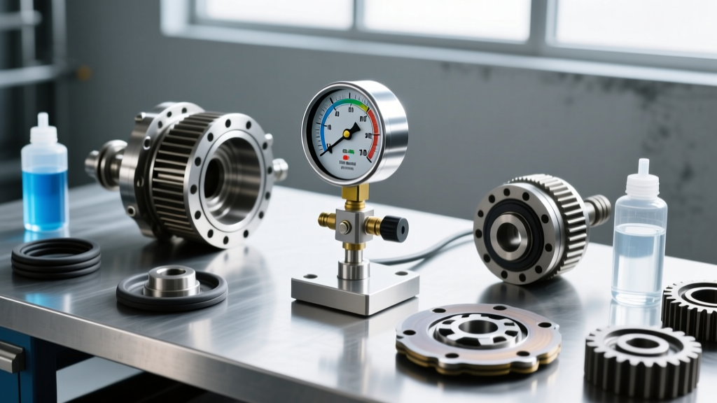
Furthermore, axle housings require a standard 0-30 PSI automotive low-pressure gauge with proper 1/4-inch NPT or flare adapters to test the cracking pressure of the axle breather valve (typically 3 to 5 PSI). Using liquid-calibrated water gauges introduces thread-sealing mismatches and scale inaccuracies that can result in over-pressurizing the housing and blowing out the pinion seal. Always use dedicated automotive pressure testing kits, such as those from Mityvac or OTC, when verifying axle housing ventilation.
Step-by-Step Differential Fluid Change Procedure (2026 Standard)
Performing a proper differential fluid change is critical to the longevity of your ring and pinion gears, bearings, and limited-slip clutch packs. Below is the definitive, step-by-step procedure for modern solid-axle and independent rear suspension (IRS) differentials.
Step 1: Temperature Preparation and Safe Lifting
Never drain a cold differential. Gear oil is highly viscous, and suspended metallic particulates will settle at the bottom of the housing when cold. Drive the vehicle for 15 to 20 minutes to bring the differential fluid up to its optimal operating temperature of approximately 140°F to 160°F. This ensures the fluid flows freely and carries abrasive metallic fines out of the housing. Safely lift the vehicle using a hydraulic floor jack and secure it on rated jack stands placed under the axle tubes or designated chassis lift points. Never rely solely on a hydraulic jack.
Step 2: Draining and Forensic Inspection
Place a high-capacity drain pan beneath the differential. Using the correct socket or hex bit (commonly 3/8-inch or 1/2-inch drive for fill/drain plugs), remove the fill plug first. This is a critical rule: if the fill plug is seized or stripped, you must know before you drain the housing, otherwise, the vehicle is immobile. Once the fill plug is removed, take out the drain plug (if equipped) or loosen the bottom three bolts of the differential cover to allow the fluid to drain into the pan.
Inspect the drained fluid and the magnetic drain plug. A fine, glitter-like metallic paste on the magnet is normal wear from the ring and pinion gears. However, if you find large metal chunks, needle bearing fragments, or excessive brass-colored shavings (indicative of thrust washer or spider gear failure), a complete differential rebuild is required. For authoritative guidelines on wear particle analysis, refer to the Dana Spicer Official Resources portal.
Step 3: Housing Cleaning and Surface Preparation
Remove the differential cover entirely. Use a dedicated gasket scraper or a plastic razor blade to remove the old RTV silicone or gasket material from both the cover and the housing mating surface. Do not use steel wire brushes, as stray bristles can fall into the housing and destroy the pinion bearings. Spray the interior of the housing with a non-chlorinated brake cleaner and wipe it down with lint-free shop towels. Standard paper towels or cheap rags will leave fibers that can clog the oil pickup channels in gerotor-style limited-slip differentials.
Step 4: Sealing and Precision Refilling
If your axle uses an RTV sealant rather than a pre-cut gasket, apply a continuous 3mm bead of a high-torque, oil-resistant silicone like Permatex Ultra Black (Part #85084) to the cover. Allow the RTV to skin over for 10 minutes before mating it to the housing to prevent silicone extrusion into the gear oil. Reinstall the cover bolts hand-tight, then torque them in a crisscross pattern to the manufacturer's specification.
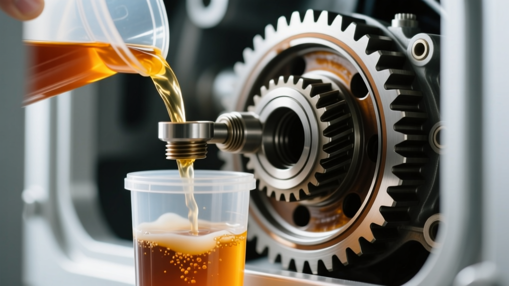
Refill the housing using a dedicated fluid transfer pump, such as the Lisle 11800, which threads directly onto standard quart bottles of gear oil. Fill until the fluid reaches the bottom edge of the fill hole. If your vehicle is equipped with a clutch-type limited-slip differential (LSD), you must add the manufacturer-specified friction modifier (e.g., Ford XL-3 or GM ACDelco 88900333) before topping off with the base gear oil to ensure proper mixing. For detailed synthetic fluid specifications and severe-duty intervals, consult AMSOIL Technical Bulletins.
Manufacturer Differential Fluid Intervals & Gear Oil Specs
The shift toward 'lifetime' fluids in the early 2010s has been largely walked back by manufacturers as towing capacities and engine torque outputs have skyrocketed. For 2026 model-year trucks and SUVs, adhering to severe-duty intervals is highly recommended if you tow, off-road, or operate in extreme temperatures.
| Vehicle / Axle Type | Normal Duty Interval | Severe Duty Interval | Recommended Fluid Spec | Capacity (Approx.) |
|---|---|---|---|---|
| Ford F-150 (10.5" Rear) | 150,000 Miles | 50,000 Miles / 3 Years | 75W-85 Synthetic API GL-5 | 2.7 Quarts |
| Ram 2500 (AAM 11.5" Rear) | 120,000 Miles | 60,000 Miles (Towing) | 75W-90 Synthetic API GL-5 | 3.8 Quarts |
| Jeep Wrangler (Dana 44 Adv.) | 50,000 Miles | 30,000 Miles (Off-Road) | 75W-140 Synthetic + Modifier | 2.0 Quarts |
| Toyota Tacoma (8.0" IRS/Solid) | 100,000 Miles | 50,000 Miles | 75W-90 API GL-5 | 2.3 Quarts |
Note: Always verify specific capacities and friction modifier requirements in your vehicle's 2026 owner's manual, as Ford Motor Company Truck Guidelines and other OEMs frequently update chemical specifications for new axle assemblies.
Torque Specifications for Common Differential Covers
Over-torquing differential cover bolts is a common mistake that leads to warped stamped-steel covers, stripped aluminum housing threads, and persistent fluid leaks. Always use a calibrated inch-pound or low-range foot-pound torque wrench.
- GM AAM 9.5" / 10.5" (14-Bolt): 25 lb-ft (34 Nm) for cover bolts; 33 lb-ft for fill/drain plugs.
- Ford 10.25" / 10.5" Sterling: 45 lb-ft (61 Nm) for cover bolts; 35 lb-ft for fill plug.
- Dana 44 / Dana 60: 30 to 35 lb-ft (40-47 Nm) for cover bolts; 25 lb-ft for fill plug.
- Chrysler 8.0" / 8.375" (IRS): 21 lb-ft (28 Nm) for cover bolts; 25 lb-ft for fill plug.
Diagnosing Internal Pressure Buildup and Breather Failures
If you are repeatedly experiencing pinion seal leaks immediately after a differential fluid change, the issue is rarely the seal itself; it is almost always a clogged axle breather valve. As the differential heats up during operation, the internal air expands. The breather valve is designed to vent this pressure while preventing water ingress during deep water fording.
If the breather becomes clogged with mud, debris, or paint from aftermarket modifications, internal pressures can exceed 15 PSI. This pressure will force gear oil past the double-lip pinion seal and axle shaft seals. To test this properly, connect a standard automotive 0-30 PSI pressure gauge to the breather hose. Submerge the axle in cold water or apply a heat gun to the housing to simulate thermal expansion. The gauge should show pressure venting at approximately 3 to 5 PSI. If pressure climbs past 8 PSI without venting, replace the breather valve immediately to prevent catastrophic fluid loss and gear seizure.