The Thermal Crisis in Modern Axle Assemblies
As 2026 heavy-duty trucks and high-performance AWD platforms push towing capacities past 40,000 pounds and track outputs beyond 800 horsepower, the thermal limitations of traditional axle assemblies have become a critical bottleneck. In a standard hypoid differential, the sliding friction between the ring and pinion gears generates immense heat. When paired with high numerical gear ratios (such as 4.10:1 or 4.30:1) and sustained heavy loads, differential fluid temperatures can easily exceed 260°F (126°C). At these thresholds, even top-tier synthetic 75W-140 gear oils experience severe shear degradation, leading to boundary lubrication failure and catastrophic gear scoring.
To combat this, the automotive aftermarket and OEM engineers have moved beyond simple finned aluminum differential covers. Modern thermal management requires active cooling loops, external filtration, and real-time telemetry. At the heart of these advanced monitoring systems lies a highly specific sensor technology. Understanding the differential pressure transducer working principle is essential for diagnosing fluid health, monitoring filter life, and preventing axle failure in extreme-duty applications.
Passive Covers vs. Active Cooling Loops
Traditional aftermarket differential covers, such as the baseline cast aluminum models, rely on passive convection and increased fluid capacity to manage heat. While increasing fluid volume from 3.5 quarts to 4.5 quarts provides a larger thermal mass, it does not actively shed heat during sustained high-load scenarios like climbing a 7% grade while towing 20,000 pounds.
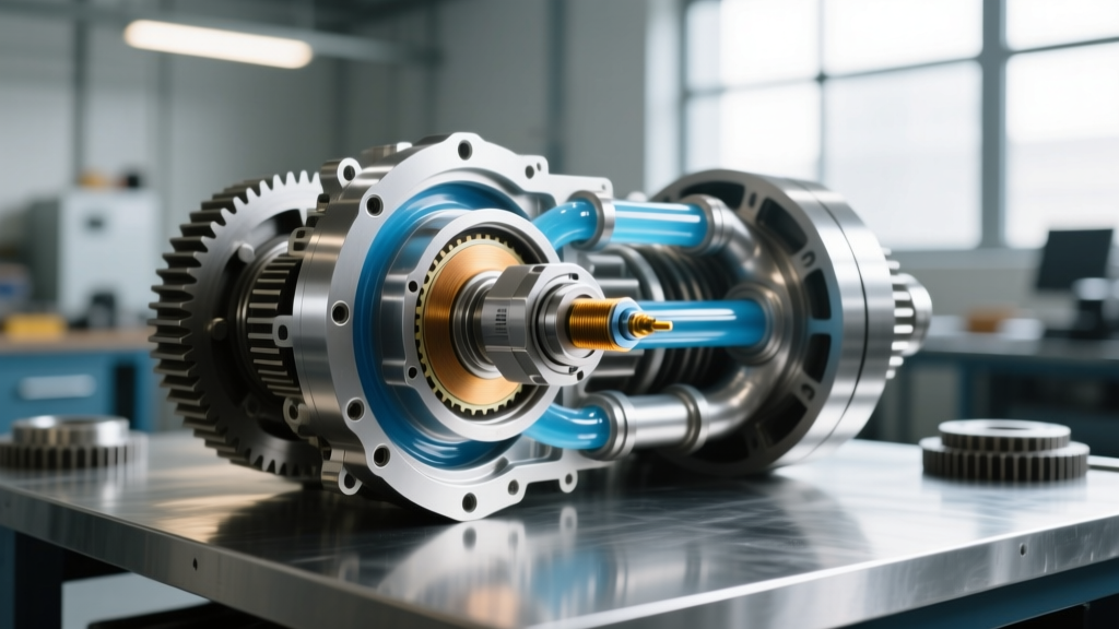
Active cooling systems utilize a PTO-driven or electric 12V gear pump to draw fluid directly from the differential sump, push it through an inline magnetic filter, route it to a front-mounted heat exchanger, and return it to the axle. Upgraded differential covers from manufacturers like Mag-Hytec or PPE (Pacific Performance Engineering) are often CNC-machined with 1/8-inch NPT or AN-6 ports specifically to accommodate the pickup tubes and return lines for these active loops.
Where the Transducer Enters the System
In any active fluid loop, the inline filter is a necessary restriction. Over time, this filter captures metallic wear debris (from the hypoid gear mesh) and carbon deposits from sheared fluid. As the filter loads with debris, the resistance to flow increases. If the filter clogs entirely, the pump will cavitate, or an internal bypass valve will open, sending unfiltered, superheated oil back into the ring gear assembly. To prevent this, engineers integrate a pressure monitoring system across the filter housing, relying entirely on the differential pressure transducer working principle to provide real-time data to the vehicle's ECU or a standalone telemetry display.
The Differential Pressure Transducer Working Principle Explained
Unlike a standard absolute pressure sensor (which measures pressure relative to a vacuum) or a gauge pressure sensor (which measures pressure relative to ambient atmospheric pressure), a differential pressure transducer measures the difference in pressure (Delta P or ΔP) between two distinct points in a fluid circuit.
Internal Architecture and MEMS Technology
Modern automotive and industrial transducers utilize Micro-Electro-Mechanical Systems (MEMS) technology. The core of the sensor is a piezoresistive silicon diaphragm. The sensor housing features two distinct fluid ports:
- High-Side Port (P1): Connected upstream of the restriction (between the pump and the filter/cooler).
- Low-Side Port (P2): Connected downstream of the restriction (the return line to the differential cover).
When gear oil flows through the system, the pressure at P1 is naturally higher than the pressure at P2 due to the restriction of the filter media and the heat exchanger tubing. This pressure differential causes the silicon diaphragm to flex. Embedded within the diaphragm is a Wheatstone bridge circuit. As the diaphragm flexes, the electrical resistance of the piezoresistors changes, unbalancing the bridge and generating a millivolt signal. An onboard ASIC (Application-Specific Integrated Circuit) amplifies this signal and converts it into a linear 0.5V to 4.5V analog output, or a digital PWM signal, which the ECU reads to calculate the exact pressure drop across the filter.
Expert Insight: According to Bosch Mobility Solutions, piezoresistive MEMS sensors offer superior thermal stability, which is critical when the sensor body is exposed to ambient engine bay temperatures while measuring hot gear oil.
Fluid Viscosity, Shear, and Delta P Telemetry
The differential pressure transducer working principle is not just useful for detecting clogged filters; it is a highly effective method for monitoring the physical health of the gear oil itself. Gear oils are graded by the SAE J306 standard, which dictates kinematic viscosity at 100°C. However, the extreme shearing forces in a hypoid gear mesh can permanently break down the viscosity index improvers in the oil.
If a 75W-140 fluid shears down to the equivalent of a 75W-90, its kinematic viscosity drops. Because thinner fluid flows through the filter and cooler with less resistance, the ECU will register an unexpected drop in Delta P, even if the filter is clean. This allows advanced fleet management systems to trigger an oil change alert based on actual fluid degradation rather than arbitrary mileage intervals.
| Fluid Specification | Kinematic Viscosity @ 100°C | Baseline ΔP (Clean) | Warning Threshold ΔP | Bypass Valve Activation ΔP |
|---|---|---|---|---|
| 75W-90 Full Synthetic | 14.5 - 18.0 cSt | 2.1 - 2.8 psi | 8.5 psi | 15.0 psi |
| 75W-140 Full Synthetic | 24.0 - 32.0 cSt | 4.2 - 5.5 psi | 14.0 psi | 22.0 psi |
| SAE 250 Racing Gear Oil | 40.0+ cSt | 8.0 - 10.5 psi | 20.0 psi | 30.0 psi |
Retrofitting Differential Covers for Active Monitoring
Integrating a differential pressure transducer into an existing axle requires precision machining and proper sealing. If you are upgrading a Dana 80, AAM 11.5, or Ford 10.5 axle for heavy towing, follow these hardware and installation specifications:
1. Cover Selection and Machining
Select a heavy-duty cover with thick flange material, such as the Mag-Hytec Dana 80 cover (Part #10153) or the PPE Cast Aluminum cover. If the cover lacks pre-drilled ports for the cooling loop, use a 1/8-inch NPT tap for the pressure sensor ports. CRITICAL: Always remove the differential cover entirely before drilling or tapping to prevent aluminum shavings from entering the ring gear assembly. Clean the cover with brake cleaner and compressed air post-machining.
2. Sensor and Fitting Installation
Use steel or anodized aluminum AN-6 to 1/8-inch NPT adapters. Wrap the NPT threads with PTFE tape or apply a liquid thread sealant like Loctite 567 to prevent gear oil weeping. Torque the sensor housing into the aluminum cover carefully; the maximum torque for 1/8-inch NPT fittings in cast aluminum is typically 10-12 lb-ft to prevent cracking the housing.
3. Differential Cover Torque Sequence
When reinstalling the differential cover, surface preparation is paramount. Scrape all old RTV from the axle housing mating surface. Apply a continuous 3mm bead of high-temp RTV (such as Permatex Ultra Black or The Right Stuff). Install the cover and torque the bolts in a crisscross star pattern to ensure even clamping force.
- 10mm Bolts (e.g., AAM 9.5/10.5): Torque to 24 lb-ft (32 Nm).
- 3/8-inch Bolts (e.g., Dana 80): Torque to 30-35 lb-ft (40-47 Nm).
- 12mm Bolts (e.g., Ford 10.5): Torque to 33 lb-ft (45 Nm).
Diagnostic Edge Cases and Troubleshooting
When tuning or diagnosing an active differential cooling system, understanding the nuances of the differential pressure transducer working principle will save hours of troubleshooting. Here are the most common edge cases encountered in the field:
False Low Delta P Codes (Sensor Reads Near Zero)
If the ECU expects a 4.5 psi drop but reads 0.2 psi, the system may flag a 'Filter Bypass' or 'Pump Failure' code. Before replacing the $85-$140 transducer, check for pump cavitation. If the suction line from the differential sump is restricted, or if the gear oil is heavily aerated (foaming due to aggressive ring gear churning without proper anti-foam additives), the pump will vapor-lock, resulting in zero fluid pressure and zero Delta P.
Sensor Drift and Thermal Shock
Gear oil temperatures can swing from 70°F at startup to 250°F under load. Inferior transducers suffer from thermal drift, where the silicon diaphragm's baseline resistance changes with temperature, skewing the Delta P reading. Always source OEM-grade or high-tier aftermarket sensors (e.g., from Bosch or Denso) that feature integrated temperature compensation algorithms. Furthermore, ensure the sensor body is isolated from extreme radiant heat sources like the exhaust DPF, as localized heating of the sensor housing can cause the fluid inside the sensor ports to expand, creating phantom pressure readings.
Conclusion
As axle assemblies are tasked with managing unprecedented torque and thermal loads, passive differential covers are no longer sufficient for extreme-duty applications. By leveraging active cooling loops and applying the differential pressure transducer working principle to monitor fluid dynamics, operators can transition from reactive repairs to predictive maintenance. Whether you are building a 2026 heavy-duty tow rig or a dedicated track AWD system, integrating Delta P telemetry is the ultimate safeguard for your ring, pinion, and drivetrain investment.