The Evolution of Electro-Hydraulic Center Differentials
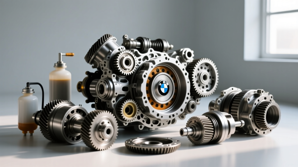
Modern All-Wheel Drive (AWD) architectures have largely abandoned purely mechanical center differentials in favor of electro-hydraulic wet-clutch couplings. Systems like the Haldex Gen 5/6, BorgWarner Torque-on-Demand, and ZF-based torque vectoring units rely on precise hydraulic pressure to distribute torque between the front and rear axles. At the heart of this operation is the differential pressure monitoring system, a critical network of sensors and control valves that ensures the clutch packs engage with exact force. When this system fails or detects anomalous pressure differentials, the vehicle defaults to front-wheel drive to protect the drivetrain, leaving the driver with a dashboard warning and compromised traction.
As we navigate the 2026 automotive landscape, the integration of DoIP (Diagnostics over Internet Protocol) and high-speed CAN-FD networks means that AWD fault codes are more granular than ever. However, the root causes of differential pressure monitoring system faults almost always trace back to fluid shear, pump starvation, or transducer degradation. This guide provides a master-level diagnostic protocol for center differential hydraulic faults.
How the Differential Pressure Monitoring System Operates
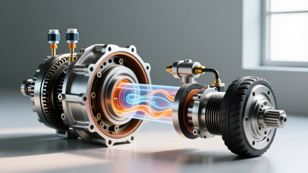
To troubleshoot effectively, you must understand the hydraulic circuit. The AWD control module (often integrated into the rear axle differential housing or mounted as a separate TCM) commands a PWM (Pulse Width Modulated) solenoid valve. This valve regulates hydraulic pressure generated by an electric gerotor pump, applying it to a multi-plate wet clutch pack.
The Physics of Clutch Pack Engagement
The differential pressure monitoring system utilizes a piezoresistive pressure transducer to measure actual line pressure in real-time. The module compares this actual pressure against the calculated target pressure based on steering angle, wheel speed delta, and throttle position. If the target pressure is 25 bar, but the transducer reports only 12 bar, the module recognizes a pressure delta fault. It will immediately ramp up the pump duty cycle. If the delta persists, it triggers a limp-mode code and disengages the rear axle to prevent clutch pack glazing or hydraulic pump burnout.
Recognizing Symptoms of Pressure Delta Faults
Before connecting a bi-directional scan tool, physical driving symptoms can often isolate the issue to the center differential's hydraulic circuit. Look for the following indicators:
- AWD Malfunction / Driveline Warning Light: Often accompanied by a message restricting vehicle speed or disabling stability control.
- FWD Default Mode: Noticeable understeer during hard cornering on wet surfaces, and a complete lack of rear-wheel torque bias during aggressive acceleration from a stop.
- High-Pitch Whining from the Rear Axle: Indicates the hydraulic pump is running at a 90%+ duty cycle, cavitating due to a clogged pickup screen or severely sheared fluid.
- Binding or Shuddering on Tight Turns: A sign that the control valve is stuck open, applying maximum clamping pressure to the center diff clutches even when the front and rear axle speeds need to differentiate.
Step-by-Step Diagnostic Protocol
Diagnosing the differential pressure monitoring system requires moving from non-invasive fluid checks to live data interrogation. Follow this sequence to avoid misdiagnosing a $600 pump when a $30 fluid service is the actual cure.
Phase 1: Fluid Shear and Contamination Analysis
The most common cause of pressure monitoring faults is fluid degradation. Wet clutch packs shed friction material, and the extreme shearing forces break down the fluid's viscosity modifiers. In Haldex Gen 5 and Gen 6 applications, the factory-recommended interval is often listed as 'lifetime' or 60,000 miles. In reality, severe-duty intervals demand a change every 20,000 to 30,000 miles.
Procedure:
- Remove the drain plug (typically an 8mm or 10mm Allen, torqued to 15 Nm).
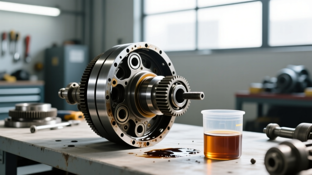
- Inspect the fluid. Fresh fluid (e.g., VAG G 060 175 A2) is translucent and amber. Sheared fluid will be opaque, dark brown, and smell distinctly of burnt friction material.
- Check for metallic glitter on the drain plug magnet. Fine brass-colored dust is normal clutch wear; steel chunks indicate bearing or gear failure.
- Drop the pump reservoir cover. In Gen 5 systems, there is no traditional inline filter; instead, a small mesh strainer sits on the pump pickup. This screen is notorious for clogging with clutch debris, starving the pump and causing the pressure monitoring system to read low pressure despite a healthy pump motor.
Phase 2: Live Data PID Interrogation
Connect an advanced bi-directional scanner capable of accessing the AWD/Transfer Case control module. Access the live data PIDs for the hydraulic circuit.
- Target Clutch Pressure vs. Actual Clutch Pressure: Command the clutches to 20 bar via active tests. If actual pressure lags behind target pressure by more than 2.5 bar, you have a hydraulic leak, a failing pump, or a stuck PWM valve.
- Pump Duty Cycle: A healthy pump should achieve 30 bar of line pressure at roughly 40-50% PWM duty cycle. If the scanner shows 85%+ duty cycle but pressure remains below 15 bar, the pump is mechanically failing or starved of fluid.
- Pressure Transducer Voltage: The sensor typically outputs a 0.5V to 4.5V signal. With the ignition ON and engine OFF (0 bar hydraulic pressure), the PID should read exactly 0.5V. If it reads 1.2V or higher at rest, the transducer has an internal short and must be replaced.
Phase 3: Electrical and Mechanical Verification
If the fluid is clean and the live data shows erratic pressure drops, perform a voltage drop test on the pump motor supply wires. Corrosion in the main chassis ground or the AWD module connector is a frequent culprit for intermittent pressure faults. Clean the connector with electronic contact cleaner and apply dielectric grease. For detailed module coding and adaptation after a pump replacement, consult the Ross-Tech AWD Control Module Wiki for VAG-specific security access codes.
AWD Center Diff Repair Cost and Specification Matrix
Below is a reference matrix for common center differential hydraulic components, utilizing popular European AWD architectures (Haldex/BorgWarner based) as a baseline. Prices reflect average 2026 market rates for OEM and high-quality aftermarket parts.
| Component | Example Part Number | Est. Cost (USD) | Torque Spec / Capacity |
|---|---|---|---|
| AWD Hydraulic Pump Motor | 0CQ 598 549 (VAG) | $450 - $650 | Mounting Bolts: 9 Nm |
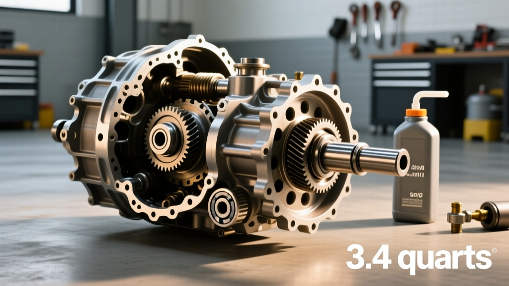
| AWD Clutch Fluid (Gen 5/6) | G 060 175 A2 | $35 - $55 / Liter | Capacity: ~0.65L / Fill Plug: 15 Nm |
| PWM Control Valve Assembly | 0CQ 598 541 | $180 - $240 | Retaining Clip: Hand Press |
| Pressure Transducer Sensor | 0CQ 598 547 | $90 - $130 | Thread Sealant Required |
| Complete Rear Coupling Assembly | Remanufactured Unit | $1,200 - $1,800 | Driveshaft Flange: 80 Nm + 90° |
Common DTCs Associated with Pressure Monitoring
When the differential pressure monitoring system detects a fault, it will log specific Diagnostic Trouble Codes. Cross-reference these with your scan tool:
- C1112 / 02248: AWD Clutch Pressure Sensor / Transducer Circuit Malfunction. Usually indicates a wiring open/short or a dead 5V reference from the module.
- C0401 / 02249: AWD Pump Motor Circuit. The module detects excessive amperage draw (pump binding) or an open circuit (corroded connector).
- P2784 / 02250: AWD Clutch Pressure Adaptation Limit Reached. The system has maxed out its software compensation for fluid shear or mechanical wear. A fluid flush and basic settings adaptation are required.
Preventative Maintenance: Beating the 'Lifetime Fluid' Myth
The concept of 'lifetime' differential and coupling fluid is a relic of early 2000s marketing, not engineering reality. The differential pressure monitoring system is only as accurate as the hydraulic medium it relies upon. For vehicles equipped with active torque-vectoring or electro-hydraulic center differentials, we mandate a fluid extraction and fill every 25,000 miles for street use, and every 15,000 miles for track or towing applications.
Always use the exact OEM-specified fluid. Friction modifiers in AWD coupling fluids are highly proprietary. Using a generic 'multi-purpose' gear oil or incorrect ATF will alter the clutch engagement coefficient, causing the pressure monitoring system to register slip faults and ultimately glazing the clutch plates. For deeper engineering insights into wet-clutch hydraulic requirements, review the BorgWarner AWD Coupling technical documentation.
By treating the AWD hydraulic circuit with the same diagnostic rigor as an automatic transmission valve body, you can accurately isolate differential pressure monitoring system faults, save customers from unnecessary $2,000 drivetrain replacements, and restore factory-level all-weather traction.